Steam condensate heat exchange system with automatic dosing device

A technology of automatic dosing and dosing device, which is applied in the field of steam condensate heat exchange system, can solve the problems of different flow directions of medicine, complicated control, and the inability to add medicine to the heat exchanger, so as to achieve the effect of improving the degree of automation

Active Publication Date: 2016-06-08
YISHENG DAHUA PETROCHEM
View PDF5 Cites 0 Cited by
  • Summary
  • Abstract
  • Description
  • Claims
  • Application Information

AI Technical Summary

Problems solved by technology

In the existing technology, the dosing device is installed at the condensate branch pipe, and the medicine is added to each condensate branch pipe respectively. The dosing device is equipped with multiple branch pipes, and each branch pipe is equipped with a control valve. The position of the heater is different, and the flow direction of the drug amount is different, which may cause the problem that the heat exchanger far away from the dosing device cannot be filled.

Method used


Image

  • Steam condensate heat exchange system with automatic dosing device

Examples


Embodiment 1

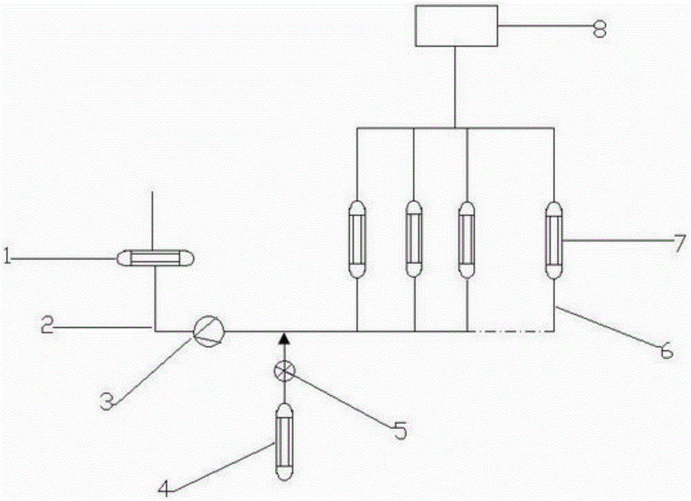
[0023] Such as figure 1 A steam condensate system with an automatic dosing device is shown, including a condenser 1, a condensate main pipe 2, a pump 3, a dosing device 4, a control valve 5, a condensate branch pipe 6 and a heat exchanger 7;

[0024] One end of the condensate main pipe 2 is provided with a steam inlet, and from the steam inlet, the condensate main pipe 2 communicates with the condenser 1 and the pump 3 successively, and the condensate main pipe 2 connected to the water outlet of the pump 3 is in parallel with a group of The condensate branch pipe 6 is connected, and the condensate branch pipe 6 is connected with a heat exchanger 7, and the terminals of the condensate branch pipe 6 are connected to each other, and are connected to the user end 8 through a connecting pipe;

[0025] The set of parallel condensate branch pipes 6 includes at least two condensate branch pipes;

[0026] The condensate main pipe 2 connected to the water outlet of the pump 3 is connec...

Embodiment 2

[0036] A steam recovery system, including a condenser 1, a condensate main pipe 2, a pump 3, a dosing device 4, a control valve 5, a condensate branch pipe 6 and a heat exchanger 7;

[0037] One end of the condensate main pipe 2 is provided with a steam inlet, and from the steam inlet, the condensate main pipe 2 communicates with the condenser 1 and the pump 3 successively, and the condensate main pipe 2 connected to the water outlet of the pump 3 is in parallel with a group of The condensate branch pipe 6 is connected, and the condensate branch pipe 6 is connected with a heat exchanger 7, and the terminals of the condensate branch pipe 6 are connected to each other, and are connected to the user end 8 through a connecting pipe;

[0038] The set of parallel condensate branch pipes 6 includes at least two condensate branch pipes;

[0039] The condensate main pipe 2 connected to the water outlet of the pump 3 is connected to the dosing device 4 through a connecting pipe.

[004...


PUM


Abstract

The invention discloses a steam condensate heat exchange system with an automatic agent-feeding device, and belongs to the field of chemical processing. The steam condensate heat exchange system comprises a condenser, a condensate main pipe, a pump, the agent-feeding device, a control valve, condensate branch pipes and a heat exchanger, a steam inlet is formed in one end of the condensate main pipe, the condensate main pipe is sequentially communicated with the condenser and the pump from the steam inlet, the condensate main pipe connected with a water outlet end of the pump is communicated with one group of parallel condensate branch pipes, the heat exchanger is connected onto the condensate branch pipes, and terminals of the condensate branch pipes are mutually communicated and connected with a user side through one connecting pipeline. The opening of an agent-feeding control valve can be automatically adjusted in real time, and the steam condensate heat exchange system solves the problem that agents cannot be fed to a heat exchanger far away from the agent-feeding device due to different dosage flow directions.

Description

technical field [0001] The invention relates to a steam condensate heat exchange system, in particular to a steam condensate heat exchange system with an automatic dosing device. Background technique [0002] With the continuous development of industry, energy issues have been paid more and more attention by people. At present, the steam in many chemical plants is processed and utilized through recycling. However, the steam is condensed through the condenser, and the condensed water may contain O 2 , CO 2 and SiO 2 and other impurities, the dissolved oxygen in it is easy to cause corrosion of pipelines and equipment, and the SiO contained in the water 2 It is easy to form scale, and the CO dissolved in the condensed water 2 Formation of weak electrolyte H 2 CO 3 , H 2 CO 3 decomposed into H + and HCO 3 - , thus affecting the PH value of the steam and causing pipeline corrosion. [0003] The compressor unit has relatively high requirements on the steam, and the i...

Claims


Application Information

Patent Timeline
Patent Type & Authority Patents(China)
IPC IPC(8): F22D11/06C02F1/00
Inventor 王建珍朱永新畅雯陈摩杰
Owner YISHENG DAHUA PETROCHEM
Why Eureka
Try Eureka