Grounding wire winding device

A grounding wire and winding technology, which is applied in the field of grounding wire winding devices, can solve the problems of low operating efficiency, heavy workload of operating personnel, and affecting power supply of the power system, so as to reduce personnel investment, shorten winding time, The effect of improving work efficiency

Inactive Publication Date: 2015-06-03
STATE GRID CORP OF CHINA +2
View PDF0 Cites 3 Cited by
  • Summary
  • Abstract
  • Description
  • Claims
  • Application Information

AI Technical Summary

Problems solved by technology

At present, when winding the ground wire, the operator manually winds the ground wire round by round to the ground rod, because the ground wire of 110kV and above is very long and heavy, and the operator manually winds the ground wire round by round. Winding around the ground rod in a circle not only requires a heavy workload for the operators, but also takes a long time for winding, which leads to low work efficiency of the operators and affects the normal power supply of the entire power system

Method used


Image

  • Grounding wire winding device
  • Grounding wire winding device

Examples


Embodiment 1

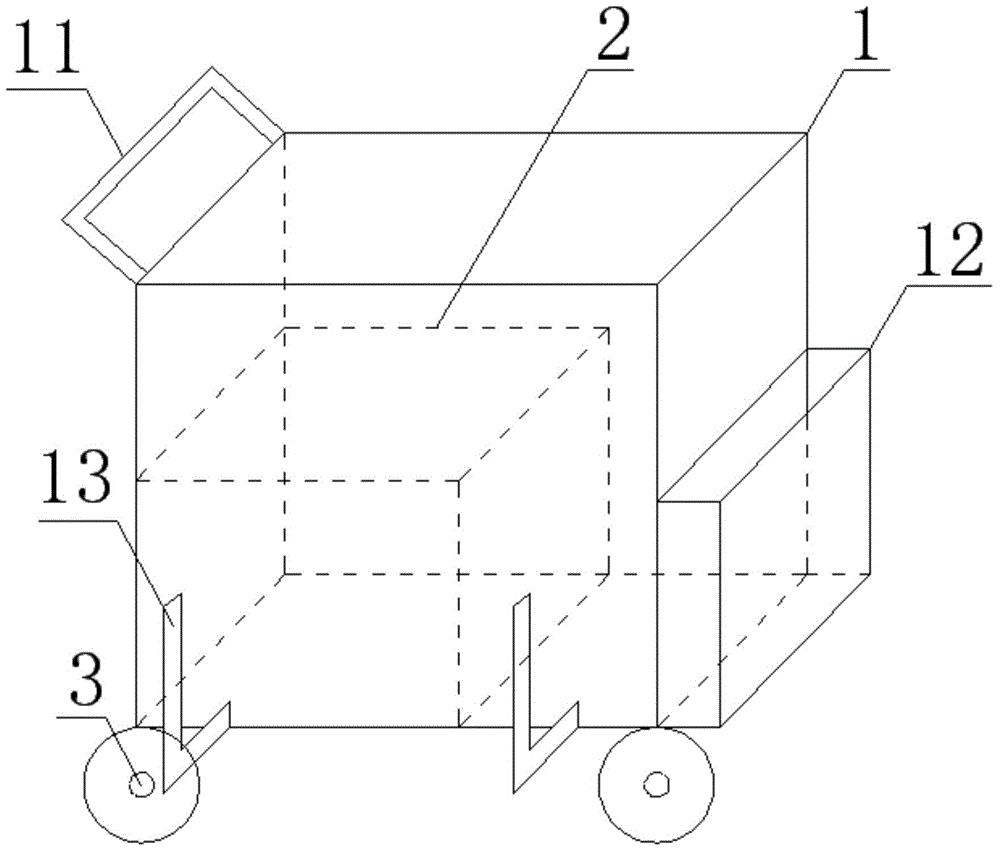
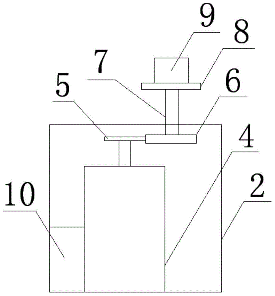
[0019] The grounding wire winding device of the present invention includes a housing 1, a winding device 2 and a wheel 3, the winding device 2 is arranged in the housing 1, and the wheels 3 are arranged at four corners at the bottom of the housing 1; The winding device 2 includes a motor 4, a first gear 5, a second gear 6, a transmission rod 7, a turntable 8, a fixed box 9 and a power junction box 10, the output shaft of the motor 4 is fixedly connected to the first gear 5, the first The gear teeth of the gear 5 and the gear teeth of the second gear 6 mesh with each other, and the center of the second gear 6 is fixedly connected to one end of the transmission rod 7, and the other end of the transmission rod 7 is fixedly connected to the bottom end of the turntable 8, and the top end of the turntable 8 is fixed Connected with a fixed box 9; one side of the motor 4 is provided with a power junction box 10, the power line of the motor 4 is connected to one end of the connection te...

Embodiment 2

[0025] The grounding wire winding device of the present invention includes a housing 1, a winding device 2 and a wheel 3, the winding device 2 is arranged in the housing 1, and the wheels 3 are arranged at four corners at the bottom of the housing 1; The winding device 2 includes a motor 4, a first gear 5, a second gear 6, a transmission rod 7, a turntable 8, a fixed box 9 and a power junction box 10, the output shaft of the motor 4 is fixedly connected to the first gear 5, the first The gear teeth of the gear 5 and the gear teeth of the second gear 6 mesh with each other, and the center of the second gear 6 is fixedly connected to one end of the transmission rod 7, and the other end of the transmission rod 7 is fixedly connected to the bottom end of the turntable 8, and the top end of the turntable 8 is fixed Connected with a fixed box 9; one side of the motor 4 is provided with a power junction box 10, the power line of the motor 4 is connected to one end of the connection te...


PUM


Abstract

The invention discloses a grounding wire winding device. The grounding wire winding device comprises a shell, a winding device and wheels, wherein the winding device is arranged in the shell and the wheels are arranged at the four end corners of the bottom end of the shell; the winding device comprises a motor, a first gear, a second gear, a transmission rod, a rotary table, a fixed box and a power supply wiring box; the output shaft of the motor is fixedly connected with the first gear; wheel teeth of the first gear are engaged with wheel teeth of the second gear; the center of the second gear is fixedly connected with one end of the transmission rod and the other end of the transmission rod is fixedly connected with the bottom end of the rotary table; the top end of the rotary table is fixedly connected with the fixed box; the power supply wiring box is arranged on one side of the motor; a power line of the motor is connected with one end of the wiring terminal of the power supply wiring box; the other end of the wiring terminal of the power supply wiring box is connected with an electric supply. By the aid of the grounding wire winding device, the winding time of a grounding wire is shortened, the labor intensity of workers is alleviated, the working efficiency is improved, and the efficiency of overhauling work is greatly improved.

Description

technical field [0001] The invention belongs to the field of substation grounding basic equipment, in particular to a grounding wire winding device. Background technique [0002] After the safety measures are removed in substation substation operation, it is often necessary to put away the grounding wire and wind it around the grounding rod according to the regulations. At present, when winding the ground wire, the operator manually winds the ground wire round by round to the ground rod, because the ground wire of 110kV and above is very long and heavy, and the operator manually winds the ground wire round by round. Winding around the ground rod in a circle not only requires a heavy workload for the operators, but also takes a long time for winding, which leads to low work efficiency of the operators and affects the normal power supply of the entire power system. Contents of the invention [0003] The purpose of the present invention is to provide a semi-automatic ground ...

Claims


Application Information

Patent Timeline
Patent Type & Authority Applications(China)
IPC IPC(8): B65H54/02B65H54/72
Inventor 何守疆周庆国
Owner STATE GRID CORP OF CHINA
Why Eureka
Try Eureka