LL type oil seal puller

A technology for external pullers and oil seals, which is applied in metal processing, metal processing equipment, hand-held tools, etc., can solve the problems of heavy workload and low oil seal efficiency, and achieve the goals of improving applicability, improving work efficiency, and shortening working hours Effect

Inactive Publication Date: 2015-06-03
CHENGDU KESHENG PETROLEUM TECH
View PDF4 Cites 7 Cited by
  • Summary
  • Abstract
  • Description
  • Claims
  • Application Information

AI Technical Summary

Problems solved by technology

Aiming at the low efficiency and heavy workload of manually pulling out the oil seal in the prior art, the present invention designs a tool that can simplify the manual operation so as to improve the pulling out efficiency; Cut out the unloading groove, and then place the U-shaped groove of the supporting base on the end face of the bearing. According to the distance between the unloading groove and the bottom of the U-shaped groove, move the pull-out rod in the hollow connecting block so that the pull-out rod The clamping disc at the end directly contacts the inner wall of the oil seal through the withdrawal groove, and then fixes the extraction rod in the connecting block through the threaded fit between the external thread and the inner wall of the connecting block, and then manually uses a wrench or other pneumatic equipment to start the alignment. The screw nut on the connecting block rotates, so that the connecting block moves upwards after being threaded with it in the through hole until the oil seal is completely pulled out; For different types of bearings, the position of the pull-out rod can be adjusted. Even if the distance between the side wall of the oil seal of each bearing and the bottom of the U-shaped groove is different, the pull-out rod can still accurately pass through the withdrawal groove and the bottom of the U-shaped groove. The inner wall of the oil seal is in contact, which greatly improves the applicability of the present invention

Method used


Image

  • LL type oil seal puller
  • LL type oil seal puller

Examples


Embodiment 1

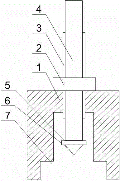
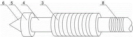
[0020] Such as figure 1 with figure 2 As shown, this embodiment includes a support base 1 with a U-shaped groove at the bottom, a through hole is opened at the upper end of the support base 1, and a pull-out rod 4 passes through the through hole and is placed in the U-shaped groove. A hollow and ring-shaped connecting block 3 is sleeved in the middle of the spool. The connecting block 3 is threaded with the through hole. An external thread 8 is also provided on the outer wall of the pull rod 4, and the external thread 8 is connected to the connecting block. The upper section of the inner wall of 3 is threaded, and the end of the pull-out rod 4 is equipped with a clamping disc 5, the outer diameter of the clamping disc 5 is greater than the outer diameter of the pull-out rod 4; also includes a nut 2, the nut 2 and The connection block 3 is threaded.

[0021] When working, manually cut the relief groove temporarily sealed on the side wall of the oil seal, then place the U-shaped ...


PUM


Abstract

The invention discloses an LL type oil seal puller. The LL type oil seal puller comprises a supporting base with a U-shaped groove in the bottom, the upper end of the supporting base is provided with a through hole, a pull-out rod penetrates the through hole to be put in the U-shaped groove, and a hollow annular connection block sleeves the middle of the pull-out rod and is in threaded fit with the through hole. The outer wall of the pull-out rod is further provided with an external thread which is matched with a thread of an upper section of an inner wall of the connection block, a clamping connection plate is mounted at the tail end of the pull-out rod, and the outer diameter of the clamping connection plate is larger than that of the pull-out rod. The LL type oil seal puller further comprises a nut in threaded fit with the connection block. The LL type oil seal puller is integrally small in structure, detachable connection of all parts can be realized to make it convenient for manual use, the pull-out rod is adjustable in position aiming at different models of bearings, and the pull-out rod is capable of accurately penetrating a withdrawal groove to contact with the inner wall of an oil seal even if a gap between an oil seal side wall of each bearing and the bottom of the U-shaped groove varies, so that applicability of the LL type oil seal puller is improved.

Description

Technical field [0001] The invention relates to an LL type oil seal, in particular to an LL type oil seal outer puller. Background technique [0002] The LL type oil seal is used to seal the 353130B compact bearing. It can achieve the purpose of preventing the short shaft of the 353130B compact bearing from bending and increasing the service life. At the same time, the use of the LL type oil seal reduces the friction torque of the entire bearing and not only avoids fretting The intrusion of abrasive particles into the bearing also makes the bearing have good sealing performance and improves the service life of grease in the bearing. [0003] However, during the long-term operation of the locomotive, in order to ensure the stable operation of the locomotive, the LL oil seal needs to be tested and replaced regularly in time. In the process of replacing the LL oil seal, the temporarily sealed oil seal withdrawal slot is usually opened. Then use pliers and other tools to pull the oil ...

Claims


Application Information

Patent Timeline
Patent Type & Authority Applications(China)
IPC IPC(8): B25B27/02B23P19/027
CPCB25B27/0028
Inventor 贺昶明
Owner CHENGDU KESHENG PETROLEUM TECH
Why Eureka
Try Eureka