
An automatic compacting device for solid particle packing

A compacting device, a technology for solid particles, applied in the separation of dispersed particles, chemical instruments and methods, separation methods, etc., can solve the problems of high control requirements of displacement and force, damage to packing, and easy jamming of cylinder pistons. Achieve the effect of ensuring safe operation, preventing jumping, and preventing volume change

Active Publication Date: 2017-03-22
WUHAN HENGYETONG GAS EQUIP
View PDF3 Cites 0 Cited by
  • Summary
  • Abstract
  • Description
  • Claims
  • Application Information

AI Technical Summary

Problems solved by technology

[0003] In the prior art, the patent No. ZL200920284082.1 describes a pressure swing adsorption oxygen generation adsorption tower mechanical compression device, which uses a compression screw and a porous platen, wherein the compression screw ensures The packing is pressed at any time under the circumstances, and the porous platen is pressed against the wall of the adsorption tower by pressing the supporting wire mesh to ensure that the packing does not leak sideways. The level cannot be adjusted; during weekly or monthly regular compaction, the control of compaction displacement and strength is high, which may easily cause the pressure plate to deflect and cause packing leakage, or excessive compaction force may cause packing damage or even pulverization
As described in the patent No. ZL98215653.7 and the patent No. ZL200820153444.9, the use of cylinder compression can realize the constant compression of the packing, and the compression force is determined by the piston area of ​​the compression cylinder. The supporting hydraulic backstop system can effectively prevent The orifice plate jumps due to excessive fluid pressure fluctuations. However, this type of device is limited by the cylinder manufacturing process. Due to the limited pressing surface of the cylinder, during the pressing displacement process, if the pressing surface is inclined, the piston of the pressing cylinder is easy to get stuck. Easy to cause filler pulverization

Method used


Image

  • An automatic compacting device for solid particle packing
  • An automatic compacting device for solid particle packing
  • An automatic compacting device for solid particle packing

Examples


Embodiment Construction

[0021] In order to better understand the present invention, the present invention will be further described below in conjunction with the accompanying drawings and specific embodiments.

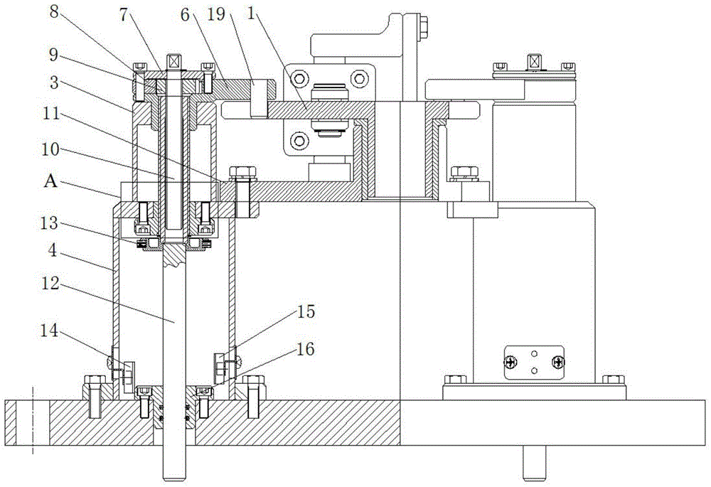
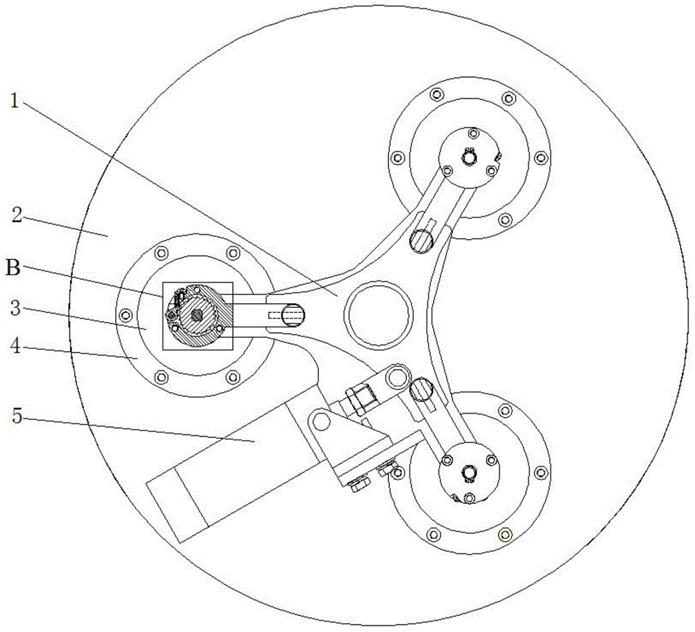
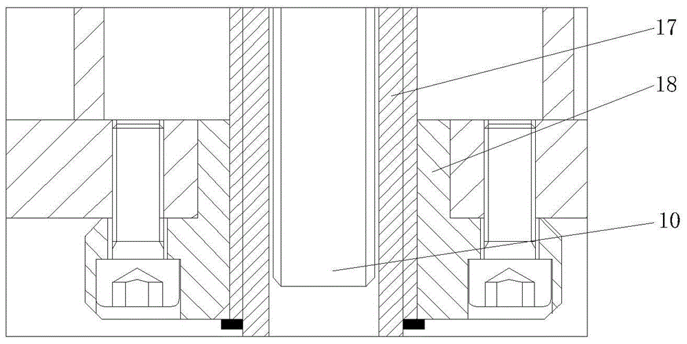
[0022] Such as Figure 1-4 In the shown automatic compacting device for solid particle packing, three cylindrical bases 4 are arranged at intervals along the tower cover 2 of the adsorption tower, and a vertical compacting rod 12 passing through the tower cover 2 is arranged inside the base 4. The lower end of the pressing rod 12 is connected with the packing pressure plate inside the adsorption tower; the top of the base 4 is provided with a cylindrical top seat 3, and the top seat 3 is provided with a driving screw 17, which is configured with a fixed screw sleeve 18; The lower end of transmission screw mandrel 17 links to each other with the upper end of hold-down bar 12, and transmission screw mandrel 17 links to each other with transmission shaft 10, and transmission shaft 10 is connecte...


PUM


Abstract

The invention discloses an automatic solid particle packing compression device. Cylindrical bases are arranged along the peripheral direction of a cover cap of an adsorption tower at intervals, and are internally provided with compression rods penetrating through the tower cap; the lower ends of the compression rods are connected with a packing pressing plate in the adsorption tower; the tops of the bases are provided with cylindrical top bases; the top bases are internally provided with drive screw rods matched with fixed swivel nuts; the lower ends of the drive screw rods are connected with the upper ends of the compression rods; the drive screw rods are connected with a drive shaft; the drive shaft is connected with a ratchet-pawl mechanism connected with a drive plate driving mechanism. According to the invention, multiple synchronous compression devices run synchronously, so that the displacement amount of each compression point is consistent, the compression force acts on packing equally and stably so as to prevent packing side leakage caused by obliqueness of the packing pressing plate due to unbalanced multi-point compression force; a pore plate can be effectively prevented from jumping after compression.

Description

technical field [0001] The invention relates to the field of chemical machinery, in particular to an automatic compacting device for solid particle fillers. Background technique [0002] In the gas separation equipment manufacturing industry, especially in the pressure swing adsorption gas separation equipment, the severe fluctuation of pressure has a great impact on the solid particle packing, which is easy to cause the fluidization of the solid particle packing, and limiting the fluid velocity can prevent fluidization. However, when the fluid movement speed cannot be reduced in the process, auxiliary equipment such as a particle packing compaction device is required to control the particle movement. In the pressure swing adsorption process, the pressure swing adsorption gas separation equipment mainly relies on the difference in the adsorption capacity and adsorption rate of the adsorbent for each component gas in the gas under different pressures to achieve the purpose of...

Claims


Application Information

Patent Timeline
Patent Type & Authority Patents(China)
IPC IPC(8): B01D53/047
Inventor 贺明星张军张文平江昱曾念东杨强李玉福
Owner WUHAN HENGYETONG GAS EQUIP
Learn More