Method for Assembling the Push Rod

A push rod and housing technology, applied in the field of push rod assembly, can solve problems such as easy assembly of disc bridges, and achieve the effect of simple tolerance compensation

Inactive Publication Date: 2017-09-12
SCHAEFFLER TECH AG & CO KG
View PDF5 Cites 0 Cited by
  • Summary
  • Abstract
  • Description
  • Claims
  • Application Information

AI Technical Summary

Problems solved by technology

However, the disk bridges, which are significantly thicker and are guided on the inner wall and have lugs for anti-twist protection, may not be easily assembled by tipping inwards and, in addition, unnecessarily increase the mass of the push rod.

Method used


Image

  • Method for Assembling the Push Rod
  • Method for Assembling the Push Rod
  • Method for Assembling the Push Rod

Examples


Embodiment Construction

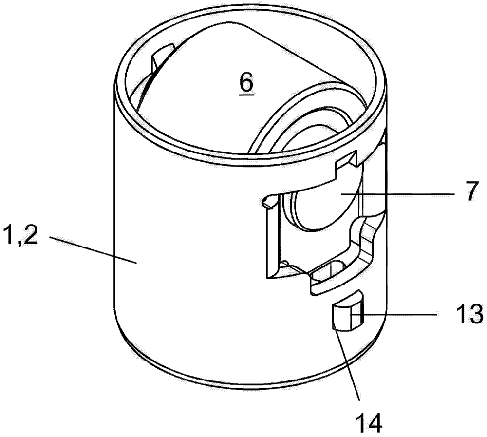
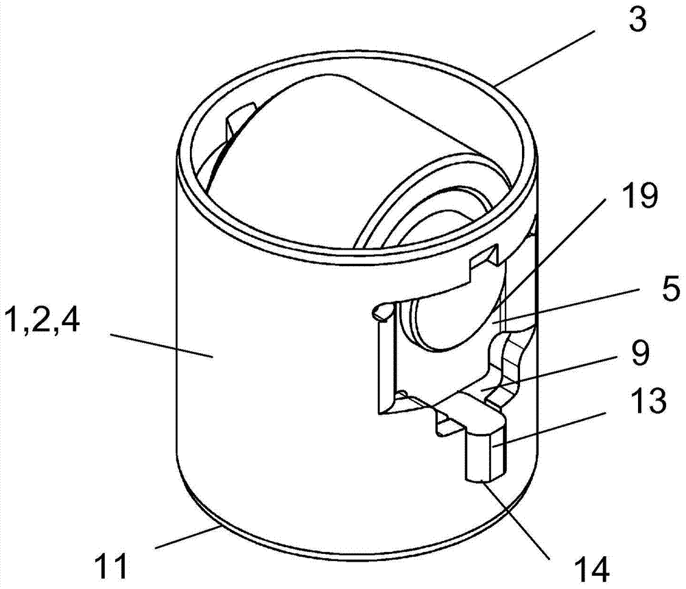
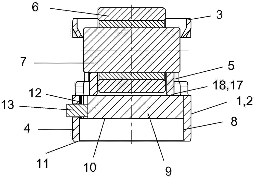
[0023] Depend on Figures 1 to 3 The pushrod 1 for the high-pressure fuel pump is known from . The push rod has a tube-like housing 2 made of steel sheet. In the drive-side annular end edge 3 of the housing 2 , two flats 5 set back from the outer peripheral side 4 of the housing 2 are diametrically opposite each other. A pin 7 is accommodated in the bore 19 of the flat part 5 , over which runs a needle-supported roller 6 for running the cam or eccentric.

[0024] The inner peripheral side 8 of the housing 2 is traversed axially below the rollers 6 by a bridge 9 which is present as a thick-walled longitudinal beam. Thus, between each longitudinal wall 20 of the bridge 9 and the inner peripheral side 8 of the housing 2 there remains a cylindrical segment-shaped surface for a relatively unhindered penetration of the lubricant.

[0025] as best from image 3 As inferred from , the bridge 9 rests against the abutment 17 in the direction of the drive-side annular end edge 3 of t...


PUM


Abstract

The invention relates to a method for mounting a plunger (1) for an injection pump. The plunger (1) has a tube-like housing (2), at the drive-side annular end face (3) of which a pin (7) carrying a roller (6) is mounted, wherein an inner jacket (8) of the housing (2) is penetrated axially below the roller (6) by a separate bridge piece (9), the lower end face (10) of which lying on one face of an output-side annular end face (11) of the housing (2) acts as a rest for a plunger-follower part, wherein the bridge piece (9) is held in the direction towards the drive-side annular end face (3) against an attachment (17) protruding inwards from the inner jacket (8) and is provided with a projection (13) protruding from the outer jacket (12) of said bridge piece. The projection (13) is guided as anti-rotation mechanism through a window (14) of the housing (2), wherein the bridge piece (9) configured as a thick-walled longitudinal beam and the projection (13) are provided as separate components, one of which is supplied first to the plunger (1) and is held there in the end position thereof or close to the end position thereof, wherein the components are then brought together in the plunger (1).

Description

technical field [0001] The invention relates to a method for assembling a push rod, in particular for a pump or a compressor, which has a pipe-like housing in which a drive-side annular end bearing a Bolt carrying rollers, wherein the inner peripheral side of the housing is traversed axially below the rollers by a separate bridge, the end of the lower bridge on the side of the annular end edge of the driven side of the housing The rim serves as abutment for the pushrod follower, wherein the bridge is held in the direction of the drive-side annular end edge on the abutment protruding from the inner peripheral side and is provided with a A lug protruding from the outer circumference, which is guided through the window of the housing as an anti-twist element. Background technique [0002] DE 10 2010 022 318 A1 discloses a pushrod for acting on a pump piston of a high-pressure fuel pump of an internal combustion engine with a relatively thin, disk-shaped bridge. The push rod c...

Claims


Application Information

Patent Timeline
Patent Type & Authority Patents(China)
IPC IPC(8): F04B1/04F04B27/04F02M59/10F01L1/14
CPCF01L1/14F01L1/143F01L2305/00F01L2305/02F01L2307/00F04B1/0408F04B53/22
Inventor 诺伯特·盖耶斯特凡·多恩
Owner SCHAEFFLER TECH AG & CO KG
Why Eureka
Try Eureka