Gain testing method and device for receiver

A test method and receiver technology, applied in receiver monitoring, electrical components, transmission systems, etc., can solve problems such as large error values ​​and affecting receiver performance, and achieve the effects of reducing errors, improving accuracy, and improving performance

Inactive Publication Date: 2015-05-27
POTEVIO INFORMATION TECH CO LTD
View PDF6 Cites 4 Cited by
  • Summary
  • Abstract
  • Description
  • Claims
  • Application Information

AI Technical Summary

Problems solved by technology

[0004] Since the tables or coefficients in the temperature compensation method are statistical data of multiple samples, they only represent the change trend of the receiver, but there are differences among the analog devices that make up the receiver, and the above-mentioned scheme cannot make up for the difference, resulting in the time of gain compensation The error value is large, which affects the performance of the receiver

Method used


Image

  • Gain testing method and device for receiver
  • Gain testing method and device for receiver
  • Gain testing method and device for receiver

Examples


Embodiment

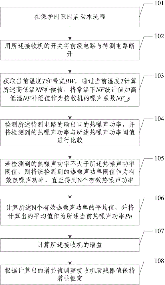
[0090] The present invention is described below with an optimal embodiment. In this embodiment, the NF statistical value at normal temperature plus the high and low temperature NF compensation value is used for illustration, but it does not limit the protection scope of the present invention. refer to image 3 , the method of this embodiment includes the following steps:

[0091] Step 101: start this process when the protection time slot is in progress;

[0092] Step 102: use the switch of the receiver to disconnect the pre-stage circuit from the circuit to be tested;

[0093] Step 103: Obtain the current temperature T and bandwidth BW, calculate the high and low temperature NF compensation value based on the current temperature T, and use the NF statistical value at room temperature plus the high and low temperature NF compensation value as the noise figure NF_s of the receiver;

[0094] Step 104: Detect the thermal noise power of the output port of the circuit under test, ...


PUM


Abstract

The invention discloses a gain testing method and device for a receiver, and relates to the technical field of wireless communication. The method comprises the following steps: acquiring the bandwidth, current thermal noise power and noise coefficient of a receiver; and computing the gain of the receiver according to the current thermal noise power, the noise coefficient and the bandwidth. The gain of the receiver is computed through the thermal noise power, so that errors generated due to differences of simulation devices are reduced, and the gain testing accuracy is increased; and meanwhile, the performance of the receiver is enhanced. Moreover, a noise system statistical value at a normal temperature and a temperature change compensation value are taken as the noise coefficient, so that the gain testing accuracy can be further increased.

Description

technical field [0001] The invention relates to the technical field of wireless communication, in particular to a receiver gain test method and device. Background technique [0002] In order to ensure the base station coverage and communication quality, the gain of the base station receiver cannot exceed a certain range. If the gain is too small, the sensitivity of the receiver will deteriorate; if the gain is too large, the anti-interference ability of the receiver will decrease. The analog devices that make up the receiver have differences in gain between different channels at the same temperature due to the process, and the gain at different temperatures of the same channel is also different. For example, in the receiver system of a TDD-LTE base station, the gain difference at normal temperature is about ±2.5dB, and the gain variation at high and low temperature is about ±5dB. If the gain is not compensated, the deterioration of sensitivity and anti-interference ability...

Claims


Application Information

Patent Timeline
Patent Type & Authority Applications(China)
IPC IPC(8): H04B17/20H04B1/06
Inventor 徐雪萍吴恂
Owner POTEVIO INFORMATION TECH CO LTD
Why Eureka
Try Eureka