


Quick Research
Generate reliable direction feasibility study reports for your R&D in just a few steps.

Technical Q&A
Discover and master advanced knowledge NOW. Basics, ideas, possibilities, all at once.

Find Solutions
As an expert in R&D theories, this can generate solutions to your technical problems instantly.

Evaluate Feasibility
Analyze your overall solution with one click, know your potential R&D risks in advance.

Monitor Landscape
Get weekly tech updates, stay abreast of the latest tech innovations and key insights.
Vehicle load sensor
A load cell and capacitive sensor technology, applied in the field of sensors, can solve the problems of sensor body damage, unusability, and scrapping, etc., to prevent sensor damage, improve service life, and accurately measure the effect.
- Summary
- Abstract
- Description
- Claims
- Application Information
AI Technical Summary
Problems solved by technology
Method used
Image

Examples
Embodiment 1
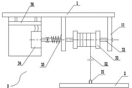
[0025] figure 1 It is a specific embodiment of the present invention. In this embodiment, the mechanical energy conversion mechanism includes a rotating shaft 31 and a return torsion spring 35. The rotating shaft 31 is located between the frame and the axle, and is arranged parallel to the frame and the axle. The bottom end of the vehicle frame is vertically provided with two support columns 11, and the rotating shaft and the support columns are assembled through bearings.
[0026] The rotating shaft is located in the middle of the two support columns and is provided with a bobbin 33, which is fixedly connected with the rotating shaft. The diameters of the two ends of the bobbin are greater than the diameter of the middle of the bobbin, and the flexible connector 32 is wound on the bobbin. The setting of the spool is used to prevent the sensor from being damaged due to the flexible connector being stuck in the bearing of the support column during the movement; on the other ha...
Embodiment 2
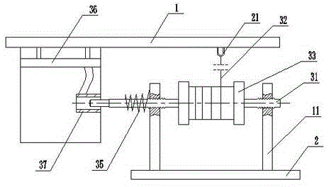
[0032] figure 2 It is another specific embodiment of the present invention. The difference between this embodiment and Embodiment 1 is: in this embodiment, the rotating shaft of the mechanical energy conversion mechanism is arranged on the vehicle axle 2 through the supporting column, and the rotating shaft and the supporting column are screwed together; in this embodiment, the pull ring 21 It is arranged on the vehicle frame 1, and the end of the flexible connector is connected to the pull ring of the vehicle frame. That is to say, in this embodiment, the mechanical energy conversion mechanism is arranged on the axle, and one end of the flexible connector is fixed on the vehicle frame, which is interchanged with the installation position of Embodiment 1.
[0033] The difference between this embodiment and Embodiment 1 lies in the structure of the measuring mechanism. In this embodiment, the measuring mechanism includes a capacitive sensor 37 and a signal conversion circuit...
Embodiment 3
[0036] The difference between this embodiment and Embodiment 2 lies in the structure of the capacitive sensor. In this embodiment, the capacitive sensor 37 includes a cylinder and a cylinder arranged in the cylinder. The cylinder of the capacitance sensor 37 is fixed on the bracket horizontally. The inner walls are in contact. When the rotating shaft moves left and right in the horizontal direction, the contact area between the capacitive sensor cylinder and the cylinder changes, that is, the capacitive signal output by the capacitive sensor changes accordingly.
PUM
 Abstract
Description
Claims
Application Information
 - R&D Engineer
- R&D Manager
- IP Professional
- Industry Leading Data Capabilities
- Powerful AI technology
- Patent DNA Extraction
Browse by: Latest US Patents, China's latest patents, Technical Efficacy Thesaurus, Application Domain, Technology Topic, Popular Technical Reports.
© 2024 PatSnap. All rights reserved.Legal|Privacy policy|Modern Slavery Act Transparency Statement|Sitemap|About US| Contact US: help@patsnap.com