
Premixed fuel nozzle for combustor and with drainage structure

A fuel nozzle and combustion chamber technology, applied in the field of gas turbine combustor nozzles and combustor premixed fuel nozzles, can solve problems such as flashback/flame adhesion, increase NOx emissions, and affect air, so as to improve uniform mixing and reduce diameter. Effects of radial velocity, uniform axial velocity distribution

Active Publication Date: 2015-05-27
CHINA UNITED GAS TURBINE TECH CO LTD
View PDF8 Cites 0 Cited by
  • Summary
  • Abstract
  • Description
  • Claims
  • Application Information

AI Technical Summary

Problems solved by technology

The uniformity of mixing can be increased to a certain extent by increasing the number of nozzles, but since the nozzles are arranged on the periphery, there will be a radial velocity component in the air flowing from the nozzles to the center, which will affect the air flow in the air cyclone flow, resulting in uneven mixing of air and fuel
Inhomogeneous mixing increases NOx emissions, affects flame stability and causes flashback / flame sticking

Method used


Image

  • Premixed fuel nozzle for combustor and with drainage structure
  • Premixed fuel nozzle for combustor and with drainage structure
  • Premixed fuel nozzle for combustor and with drainage structure

Examples


Embodiment Construction

[0017] The specific implementation manners of the present invention will be further described in detail below in conjunction with the accompanying drawings and embodiments. The following examples are used to illustrate the present invention, but are not intended to limit the scope of the present invention.

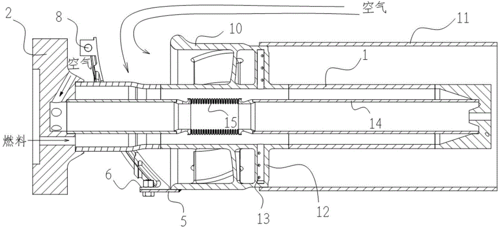
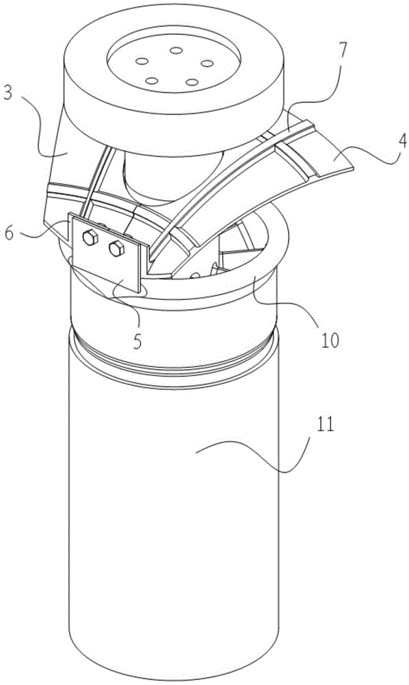
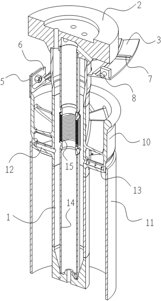
[0018] Such as figure 1 with figure 2 As shown, the premixed fuel nozzle includes an outer tube 1, a suspension flange 2, an inner tube 14, an air swirler 10, a cup sleeve 11, a fuel injection column 12, a fuel injection hole 13 and a bellows 15; the inner tube 14 and the outer tube A fuel gas channel is formed between the tubes 1 , an air channel is inside the inner tube 14 , and an air swirler is arranged outside the outer tube 1 and communicated with the fuel gas channel. The air passes through the air swirler 10 to generate a swirling flow, and the fuel gas enters the fuel gas channel from the suspension flange 2, and is sprayed out through the fuel injection hole 1...


PUM


Abstract

The invention belongs to the technical field of gas turbines and relates to a premixed fuel nozzle for a combustor and with a flow glide structure. The nozzle comprises a suspension flange, an outer pipe, an inner pipe, an air cyclone and the flow glide structure, wherein the flow glide structure is arranged between the suspension flange and the air cyclone; the flow glide structure comprises a first air flow glide plate, a second air flow glide plate and a flow glide plate installing plate, wherein the windward face of the first air flow glide plate and the windward face of the second air flow glide plate are in arc shapes, one side of the first air flow glide plate and one side of the second air flow glide plate are respectively embedded on the outer pipe and are symmetrically distributed relative to the axis of the outer pipe, one end of the first air flow glide plate and one end of the second air flow glide plate are arranged on the air cyclone through the flow glide plate installing plate, and the other end of the first air flow glide plate and the other end of the second air flow glide plate are suspended in the air. The flow glide structure can effectively reduce the radial speed of air at an inlet of the air cyclone, improves the air axial speed distribution at the inlet of the air cyclone, improves mixing between fuel and the air, effectively reduces NOx emission and avoids tempering and flame attachment.

Description

technical field [0001] The invention relates to a gas turbine combustion chamber nozzle, in particular to a combustion chamber premixed fuel nozzle with a drainage structure, belonging to the technical field of gas turbines. Background technique [0002] A specific dry low NOx emission combustion system includes multiple combustion chambers arranged in an annular array around the axis of the turbine rotor, each combustion chamber mixes air and fuel prior to combustion, and then ignites the mixture, resulting in high temperature and high pressure combustion gas. The fuel injection system for various combustion chambers consists of a plurality of fuel nozzles mounted on an end cover at the upstream end of the combustion chamber. If the fuel and air are not mixed well before combustion, localized hot spots can form in the combustion chamber. Localized hotspots can increase NOx emissions and increase the chance of flames in the combustion chamber flashing back into the nozzle ...

Claims


Application Information

Patent Timeline
Patent Type & Authority Applications(China)
IPC IPC(8): F23R3/02
Inventor 刘小龙查筱晨张珊珊张龙
Owner CHINA UNITED GAS TURBINE TECH CO LTD
Learn More