Turn-over limit pin device

A technology of limit pins and limit rods, which is applied in the direction of bolts, etc., can solve the problems of incomplete unloading, safety accidents, unscientific design, etc., and achieve the goal of eliminating shedding phenomenon, strong safety performance and scientific design Effect

Inactive Publication Date: 2015-05-27
宋莉
View PDF0 Cites 0 Cited by
  • Summary
  • Abstract
  • Description
  • Claims
  • Application Information

AI Technical Summary

Problems solved by technology

It can be proved in practice that the currently commonly used domestic flipping limit pins and limit pin plates are not firmly connected, which is easy to cause falling off and safety accidents; Thorough, manual assistance is required

Method used


Image

  • Turn-over limit pin device

Examples


Embodiment Construction

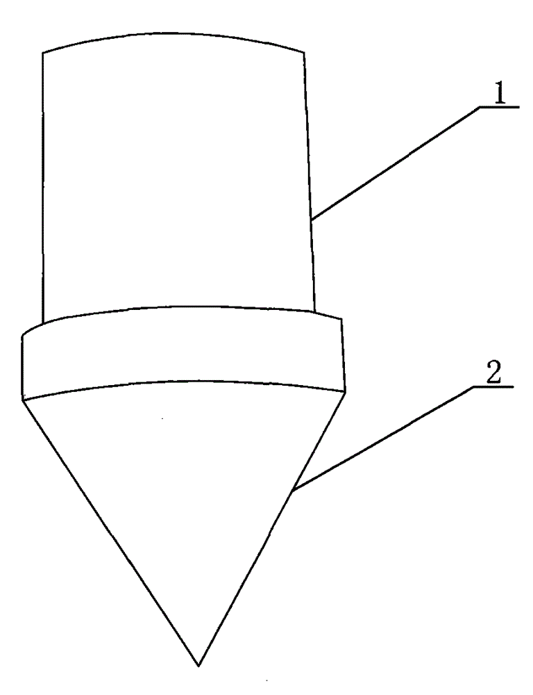
[0016] A flipping limit pin device is composed of a limit rod (1) and a limit pin base (2). The limit rod (1) is located at the upper part and is connected with the limit pin base (2).

[0017] When working: the upper end of the limit rod (1) is connected to the limit pin plate by welding. When the mine car needs to be turned over to unload the goods, the miner pushes the box of the truck, which drives the limit pin to move forward in turn, and the limit pin base (2 ) is closely combined with the pallet hole of the overturned pallet frame on the mine car, so that the box of the truck is tilted to achieve the purpose of unloading the goods.

[0018] The above-described embodiment is only one of the preferred embodiments of the present invention, and is not intended to limit the protection scope of the present invention, so: all equivalent changes made according to the shape, structure and principle of the present invention should be covered by the scope of the present invention...


PUM

PropertyMeasurementUnit
Lengthaaaaaaaaaa

Abstract

The invention discloses a turn-over limit pin device. The turn-over limit pin device is composed of a limit rod (1) and a limit pin pedestal (2), and the limit rod (1) is located at the upper part and connected with the limit pin pedestal (2). The turn-over limit pin device is scientific in design, strong in safety performance, difficult to fall off, complete in goods unloading and broadly suitable for the mining machinery field; the turn-over limit pin device is an ideal product for replacing a normal turn-over limit pin at present.

Description

technical field [0001] The invention relates to the field of mining machinery, in particular to an overturn limit pin device. Background technique [0002] The overturn limit pin is one of the mechanical components of the mine car commonly used by mining enterprises. Its main function is to make the mine car body tilt continuously with the sequential movement of the overturn limit pin, so as to realize the purpose of emptying the cargo in the car body. It can be proved in practice that the currently commonly used domestic flipping limit pins and limit pin plates are not firmly connected, which is easy to cause falling off and safety accidents; Thorough, need human assistance to complete. Therefore, it is necessary to further improve it. Contents of the invention [0003] The present invention can effectively overcome the above-mentioned shortcomings, and provide a turn-over limit pin device with scientific design, strong safety performance, not easy to fall off, and comp...

Claims


Application Information

Patent Timeline
IPC IPC(8): F16B19/02
CPCF16B19/02
Inventor 宋莉
Owner 宋莉
Why Eureka
Try Eureka