Steam turbine plant activation control device
A technology for steam turbines and equipment, which is applied in the direction of steam engine devices, mechanical equipment, engine control, etc., can solve the problems of temperature prediction calculation and thermal stress calculation and calculation processing, and achieve the effect of simplifying calculation and processing
- Summary
- Abstract
- Description
- Claims
- Application Information
AI Technical Summary
Problems solved by technology
Method used
Image
Examples
no. 1 approach
[0037] (structure)
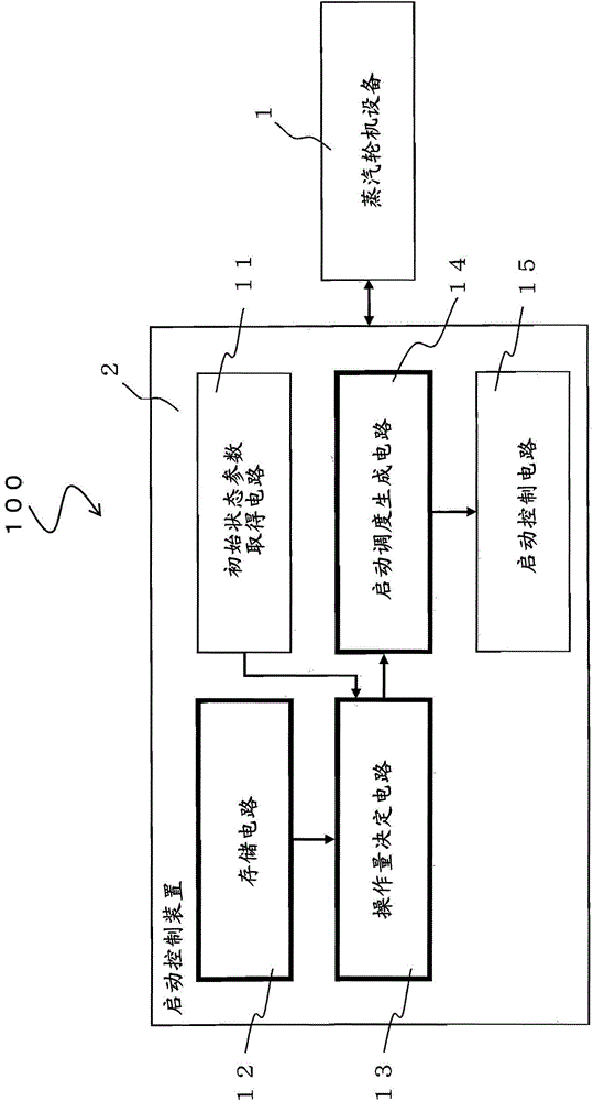
[0038] figure 1 It is a system structure diagram of the steam turbine power generation equipment 100 of the present invention. like figure 1 As shown, a steam turbine power generation facility 100 is composed of a steam turbine facility 1 and a startup control device (plant control device) 2 . Hereinafter, the steam turbine facility 1 and the start-up control device 2 will be described.
[0039] 1. Steam turbine equipment
[0040] The steam turbine facility 1 includes a heat source device, a steam generating facility, a steam turbine, a generator, a regulator, and the like, which are not shown.
[0041] The heat source device uses the heat retained in the heat source medium to heat the low-temperature fluid to generate high-temperature fluid, and supplies the generated high-temperature fluid to the steam generating device. For example, the heat source device includes a gas turbine of a combined cycle power generation facility, a furnace of a coal-fire...
no. 2 approach
[0124] (structure)
[0125] Figure 4 It is a system configuration diagram of the steam turbine power generation facility 101 of this embodiment. exist Figure 4 In , the same reference numerals are assigned to the same parts as those in the first embodiment described above, and explanations thereof are appropriately omitted.
[0126] The start control device 2 of this embodiment differs from the first embodiment in that it further includes a required start time calculation circuit 21 and an output circuit 22 . A description will be given in order centering on differences from the first embodiment.
[0127] 1. It is necessary to start the time calculation circuit
[0128] exist Figure 4 Here, the operation amount determination circuit 13 calculates the phase duration τ(θ) in the same manner as in the first embodiment, and outputs it to the required start-up time calculation circuit 21 .
[0129] The required start-up time calculation circuit 21 inputs the duration τ(θ) ...
no. 3 approach
[0144] (structure)
[0145] Figure 6 It is a system configuration diagram showing the steam turbine power generation facility 102 of this embodiment. exist Figure 6 In , the same reference numerals are given to the same parts as those in the above-mentioned second embodiment, and description thereof will be appropriately omitted.
[0146] This embodiment differs from the second embodiment in that the substitute output circuit 22 includes an activation start time calculation circuit 31 and an input / output circuit 32 . A description will be given in order centering on differences from the second embodiment.
[0147] In this embodiment, it is necessary for the start-up time calculation circuit 21 to change the state quantity parameter (in this embodiment, the elapsed time θ after stop) of the steam turbine plant 1, and use any number of pre-calculated elapsed time θ after stop and The required start time Φ(θ) is calculated from the data of the required start time Φ(θ) corre...
PUM
 Abstract
Description
Claims
Application Information
 - R&D
- Intellectual Property
- Life Sciences
- Materials
- Tech Scout
- Unparalleled Data Quality
- Higher Quality Content
- 60% Fewer Hallucinations
Browse by: Latest US Patents, China's latest patents, Technical Efficacy Thesaurus, Application Domain, Technology Topic, Popular Technical Reports.
© 2025 PatSnap. All rights reserved.Legal|Privacy policy|Modern Slavery Act Transparency Statement|Sitemap|About US| Contact US: help@patsnap.com


