
Apparatus and method for image interpolation based on low pass filtering

a low-pass filtering and image interpolation technology, applied in the field of apparatus and a method for image interpolation, can solve the problems of deteriorating objective and subject picture quality, flat panel display deterioration of standard definition broadcasting images or digital video disc images, etc., and achieve the effect of simplifying the computing process and increasing processing speed

Active Publication Date: 2012-06-26
CHUNG ANG UNIV IND ACADEMIC COOP FOUND
View PDF6 Cites 4 Cited by
  • Summary
  • Abstract
  • Description
  • Claims
  • Application Information

AI Technical Summary

Benefits of technology

This approach simplifies the computing process, increases processing speed, and effectively prevents image blurring or blocking effects, resulting in high-quality images by smoothing region boundaries and reducing errors in pixel value allocation.

Problems solved by technology

While these flat panel displays have a display area and resolution wider and higher than those of CRTs, the flat panel displays deteriorate the picture quality of standard definition (SD) broadcasting images or digital video disc (DVD) images other than high definition (HD) images when the SD broadcasting images or DVD images are displayed on the flat panel displays because these images have a resolution of 720×480i.
Furthermore, if the resolution of an image displayed on a flat panel display does not correspond to the resolution of the flat panel display, pixels of the flat panel display are not one-to-one matched to the image, and thus the image is indistinctly displayed on a screen of the flat panel display to cause objective and subject picture quality deterioration.

Method used


Image

  • Apparatus and method for image interpolation based on low pass filtering
  • Apparatus and method for image interpolation based on low pass filtering
  • Apparatus and method for image interpolation based on low pass filtering

Examples


Embodiment Construction

[0020]Hereinafter, an image interpolating apparatus and method according to an embodiment of the present invention will be described below with reference to the accompanying drawings.

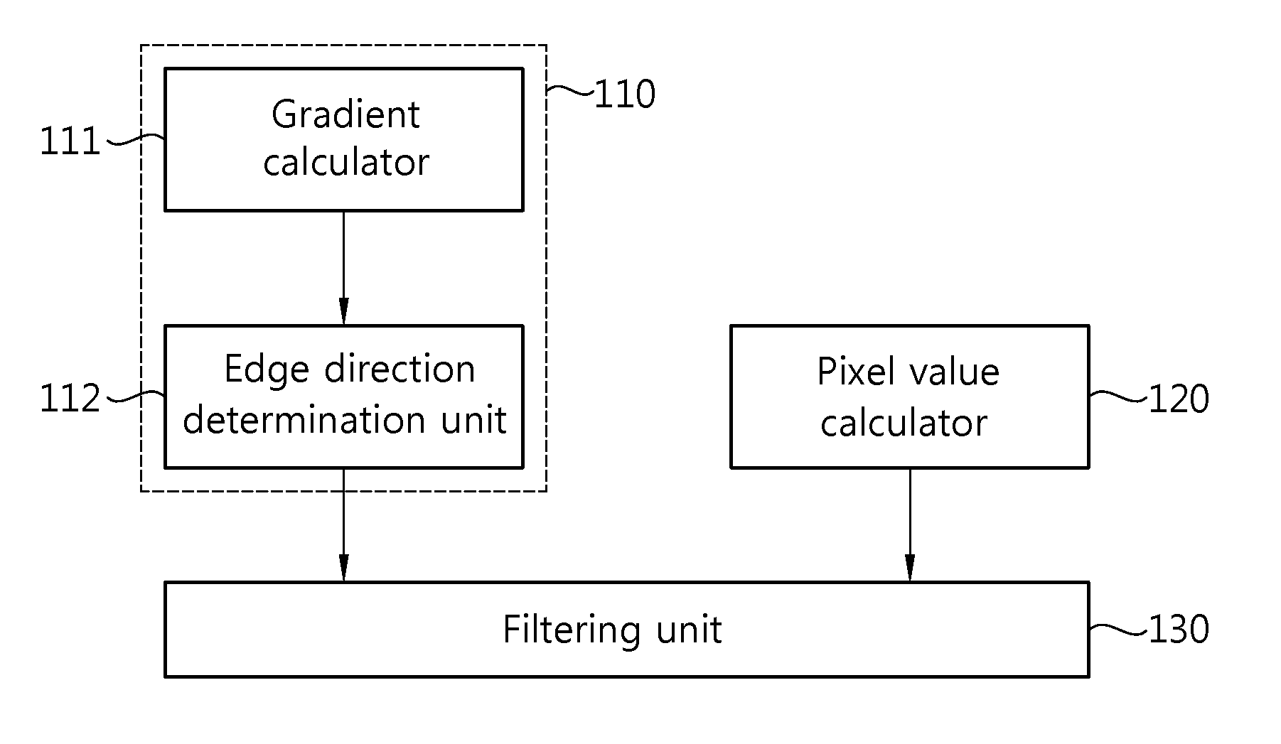
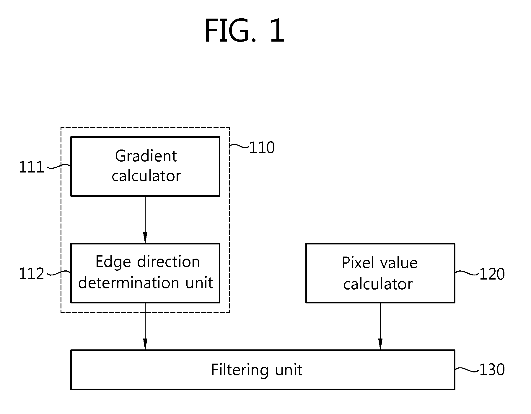
[0021]FIG. 1 is a block diagram of an apparatus for image interpolation based on low pass filtering according to an embodiment of the present invention.

[0022]Referring to FIG. 1, the image interpolating apparatus based on low pass filtering according to an embodiment of the present invention includes an edge direction detector 110, a pixel value calculator 120 and a filtering unit 130.

[0023]The edge direction detector 110 detects the direction of an edge corresponding to a pixel nearest to a to-be-interpolated pixel to which a pixel value will be allocated among pixels having determined pixel values in an image frame and determines the detected edge direction as an edge direction of the to-be-interpolated pixel. The edge direction detector 110 includes a gradient calculator 111 and an edge direction det...


PUM


Abstract

An apparatus and method for image interpolation based on low pass filtering are provided. The apparatus includes an edge direction detector detecting an edge direction for a pixel nearest to a to-be-interpolated pixel among pixels and determining the edge direction of the to-be-interpolated pixel as the detected edge direction, a pixel value calculator calculating pixel values of interpolation points located in a lattice filtering window having a predetermined size by using pixel values of pixels located adjacent to the interpolation points, and a filtering unit performing low pass filtering on the to-be-located pixel according to a low pass filter corresponding to the determined edge direction of the to-be-interpolated pixel, the low pass filter being one of low pass filters corresponding to predetermined vertical, horizontal, left diagonal and right diagonal directions respectively. Accordingly, a process of calculating the pixel value of the to-be-interpolated pixel can be simplified and a processing speed can be increased. Furthermore, it is possible to obtain a high-quality image without having image deterioration such as blocking effect caused by an error in a pixel value even for a region with an uneven edge.

Description

CROSS-REFERENCE TO RELATED APPLICATIONS[0001]This application claims the benefit of priority of Korean Patent Application No. 10-2008-0025773 filed on Mar. 20, 2008, which are incorporated by reference in their entirety herein.BACKGROUND[0002]1. Field of the Invention[0003]The present invention relates to an apparatus and a method for image interpolation, and more particularly, to an apparatus and a method for allocating a new pixel value to a to-be-interpolated pixel of an image frame to improve the resolution of an image corresponding to the image frame.[0004]2. Related Art[0005]Flat panel displays such as a liquid crystal display (LCD) and a plasma display panel (PDP) have rapidly replaced conventional cathode-ray tubes (CRT) in the recent large-sized display market.[0006]While these flat panel displays have a display area and resolution wider and higher than those of CRTs, the flat panel displays deteriorate the picture quality of standard definition (SD) broadcasting images or ...

Claims


Application Information

Patent Timeline
Patent Type & Authority Patents(United States)
IPC IPC(8): G06K9/40G06K9/32
CPCG06T3/403H04N5/208H04N5/21
Inventor JOON-KI, PAIKYOO, YOON-JONGYOUN, JIN-YOUNGKIM, DONG-GYUNSHIN, JEONG-HO
Owner CHUNG ANG UNIV IND ACADEMIC COOP FOUND
Learn More