Inductive wire end cutting device

A technology of inductance wire and inductance, which is applied in the field of cutting devices for excessively long leads at both ends of the inductance. It can solve the problems of inconsistent length, low production efficiency, and poor stability, and achieve the effects of increased production efficiency, reduced labor intensity, and good stability.

Active Publication Date: 2015-05-27
广西昭信平洲电子有限公司
View PDF6 Cites 0 Cited by
  • Summary
  • Abstract
  • Description
  • Claims
  • Application Information

AI Technical Summary

Problems solved by technology

[0003] The purpose of the present invention is to provide an inductor lead cutting device to solve the problems of inconsistency, poor stability and low production efficiency in the existing inductance both ends of excessively long lead wire cutting

Method used


Image

  • Inductive wire end cutting device
  • Inductive wire end cutting device
  • Inductive wire end cutting device

Examples


Embodiment Construction

[0015] The present invention will be described in further detail below in conjunction with accompanying drawing embodiment:

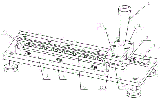
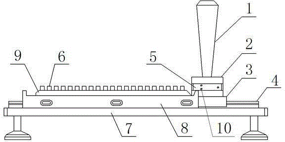
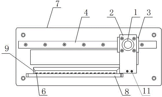
[0016] Such as Figure 1 to Figure 5 The shown inductance lead cutting device includes a base 7 and a positioning seat 9 arranged on the base 7, and a plurality of guides corresponding to the inductance 13 installed on the printing stick 12 are provided at intervals on the top of the positioning seat 9. Block 6, on one side of the positioning seat 9, a rod seat 8 with a gap at the top is provided, on the other side of the positioning seat 9, a guide rail 4 is provided on the base 7, and the guide rail 4 is connected with the knife rest 2 through the guide sleeve 3 , the knife rest 2 is provided with a blade mounting part that stretches out and is placed above the positioning seat 9; the positioning seat 9 is arranged in parallel with the guide rail 4; the knife rest 2 is provided with a handle 1; the positioning seat 9 is provided with a On an inclined...


PUM


Abstract

The invention discloses an inductive wire end cutting device, and relates to the technical field of inductive manufacturing equipment. The device comprises a base and a locating seat arranged on the base, wherein a plurality of guide blocks corresponding to an inductor on a bar are alternately arranged at the top of the locating seat, and a gap is formed in the top of a bar seat; one side of the locating seat is provided with the bar seat, and the other side of the locating seat is provided with a guide rail on the base, the guide rail is connected with a knife rest through a guide sleeve and the knife rest is provided with a blade mounting part protruding above the locating seat. Compared with the prior art, the inductive wire end cutting device is simple in structure, convenient to operate and high in production efficiency, the consistent length sizes of wires at the two ends of the inductor can be ensured, and the labor intensity of workers can be reduced at the same time.

Description

technical field [0001] The invention relates to the technical field of inductance equipment manufacturing, in particular to a cutting device for excessively long leads at both ends of an inductance. Background technique [0002] Inductor is an electromagnetic induction element wound with insulated wires, and it is also one of the commonly used components in electronic circuits. The length of the leads used to connect other components at both ends of the inductor needs to be cut according to different requirements. At present, the cutting method of the excessively long leads at both ends of the inductor is as follows: Figure 5 As shown, a plurality of inductors (13) are arranged and installed in the holder of the printing stick (12), and then the excessively long lead wires at both ends of each inductor are cut off according to requirements by manually using scissors. The method of cutting off the overlong leads at both ends of the inductor has the following deficiencies in ...

Claims


Application Information

Patent Timeline
Patent Type & Authority Applications(China)
IPC IPC(8): B21F11/00
CPCB21F11/00
Inventor 潘耀梅沙永恒姜普
Owner 广西昭信平洲电子有限公司
Why Eureka
Try Eureka