Power system transformer substation communication equipment power supply with embedded direct-current power supply module structure
A DC power supply system and DC power supply technology, applied in the direction of conversion equipment without intermediate conversion to AC, electrical components, output power conversion devices, etc., can solve problems such as increasing fault points and reducing power use efficiency, and achieve good safety performance , easy maintenance, and optimize the effect of the DC conversion process
- Summary
- Abstract
- Description
- Claims
- Application Information
AI Technical Summary
Problems solved by technology
Method used
Image

Examples
Embodiment 1
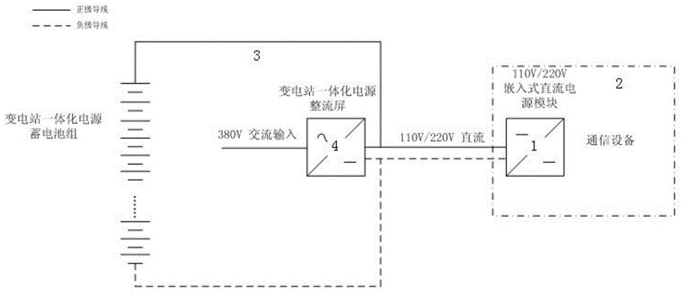
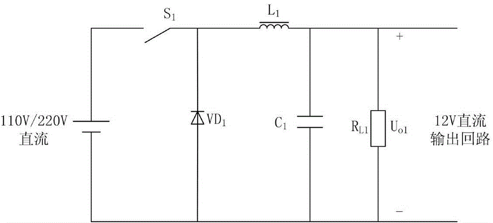
[0029] Examples, refer to Figure 2 to Figure 3 In the power system power system substation communication equipment power supply with embedded DC power module structure shown, the voltage conversion circuit for converting 110V / 220V DC input voltage to 12V DC output voltage is composed of power switch S1, inductor L1, diode VD1, capacitor C1 and resistor RL1 are connected; capacitor C1 and resistor RL1 are connected in parallel, the cathode of diode VD1 is connected to one end of the parallel group of capacitor C1 and resistor RL1 through inductor L1, and the anode of 110V / 220V DC input power is connected to the cathode of diode VD1 through power switch S1 , forming the positive terminal of the 12V DC output voltage; the positive terminal of the diode VD1 is connected to the other end of the parallel connection of the capacitor C1 and the resistor RL1 and the negative terminal of the 110V / 220V DC input power supply, forming the negative terminal of the 12V DC output voltage.
...
Embodiment 2
[0036] The technical characteristics of present embodiment 2 are: as Figure 4 As shown, the voltage conversion circuit for converting 110V / 220V DC input voltage to 5V DC output voltage is formed by connecting power switch S2, inductor L2, diode VD2, capacitor C2 and resistor RL2; capacitor C2 and resistor RL2 are connected in parallel, The negative pole of diode VD2 is connected to one end of the parallel group of capacitor C2 and resistor RL2 through inductor L2, and the positive pole of 110V / 220V DC input power is connected to the negative pole of diode VD2 through power switch S2 to form the positive pole of 5V DC output voltage; the positive pole of diode VD2 is connected to The other end of the capacitor C2 and the resistor RL2 are connected in parallel to the negative terminal of the 110V / 220V DC input power supply to form the negative terminal of the 5V DC output voltage.
[0037] The input and output voltage characteristic indicators in this embodiment are as follows:...
Embodiment 3
[0043] The technical characteristics of present embodiment 2 are: as Figure 5 As shown, the voltage conversion circuit for converting 110V / 220V DC input voltage to 3V DC output voltage is formed by connecting power switch S3, inductor L3, diode VD3, capacitor C3 and resistor RL3; capacitor C3 and resistor RL3 are connected in parallel, The negative pole of diode VD3 is connected to one end of the parallel group of capacitor C3 and resistor RL3 through inductor L3, and the positive pole of 110V / 220V DC input power is connected to the negative pole of diode VD3 through power switch S3 to form the positive pole of 3V DC output voltage; the positive pole of diode VD3 is connected to The other end of the capacitor C3 and the resistor RL3 are connected in parallel to the negative terminal of the 110V / 220V DC input power supply to form the negative terminal of the 3V DC output voltage.
[0044] The input and output voltage characteristic indicators in this embodiment are as follows:...
PUM
 Abstract
Description
Claims
Application Information
 - Generate Ideas
- Intellectual Property
- Life Sciences
- Materials
- Tech Scout
- Unparalleled Data Quality
- Higher Quality Content
- 60% Fewer Hallucinations
Browse by: Latest US Patents, China's latest patents, Technical Efficacy Thesaurus, Application Domain, Technology Topic, Popular Technical Reports.
© 2025 PatSnap. All rights reserved.Legal|Privacy policy|Modern Slavery Act Transparency Statement|Sitemap|About US| Contact US: help@patsnap.com