Detection tool structure for shaft positioning groove of automobile connecting rod

An automobile connecting rod and shaft positioning technology, applied in the direction of mechanical depth measurement, etc., can solve the problems of time-consuming detection and complicated operation, and achieve the effects of convenient calibration, improved measurement accuracy, and small axial expansion

Inactive Publication Date: 2015-05-20
MT PRECISION MACHINERY MFG
View PDF0 Cites 0 Cited by
  • Summary
  • Abstract
  • Description
  • Claims
  • Application Information

AI Technical Summary

Problems solved by technology

[0002] An automobile connecting rod, comprising a large connecting rod end and a small connecting rod end. A shaft positioning groove is arranged on the inner side of the shaft hole of the large connecting rod end. It is difficult for existing dial gauges to check the depth of the shaft positioning groove, that is, the lower end surface of the shaft positioning groove and the The distance between the upper end face of the big end of the connecting rod is measured
Generally, the depth of the shaft positioning groove is measured by a three-coordinate detection machine, but the operation is complicated and the detection is time-consuming

Method used


Image

  • Detection tool structure for shaft positioning groove of automobile connecting rod
  • Detection tool structure for shaft positioning groove of automobile connecting rod

Examples


Embodiment Construction

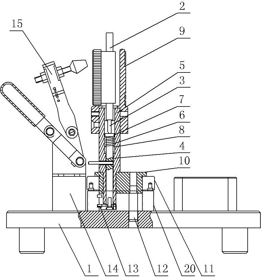
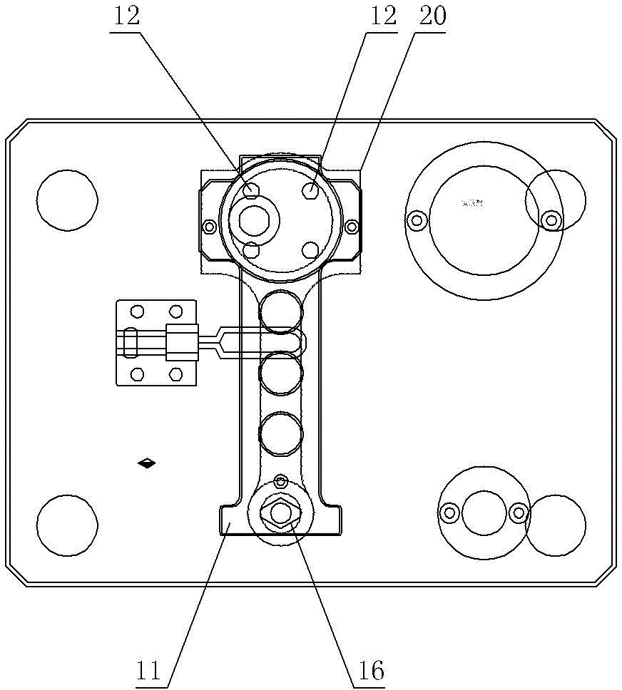
[0018] like figure 1 , figure 2 As shown, the inspection tool structure of the shaft positioning groove of the automobile connecting rod includes a bottom plate 1 and a measuring table device. The positioning pin is arranged on the bottom plate 1, and the measuring rod head of the measuring table device is provided with the shaft positioning groove of the automobile connecting rod. The matching positioning protrusion 13, the positioning protrusion 13 is located at the radial outside of the measuring rod; the measuring gauge device includes a dial indicator 2, a gauge body 5 and a measuring rod, the gauge body 5 is provided with an axial perforation, and the perforation of the gauge body 5 The upper part is equipped with a dial indicator 2, the lower part of the perforation is equipped with a measuring rod 4, and the measuring rod 3 of the dial indicator is installed on the upper end surface of the measuring rod 4; Notch one 7, the spring 6 is also set on the measuring rod 4,...


PUM


Abstract

The invention provides a detection tool structure for a shaft positioning groove of an automobile connecting rod. The detection tool structure is simple in operation and rapid in detection. The detection tool structure comprises a bottom plate and a measuring meter device, and is characterized in that the bottom plate is equipped with a positioning pin, the head of a measuring rod of the measuring meter device is equipped with a positioning bulge matching the shaft positioning groove of the automobile connecting rod, and the positioning bulge is located at the radial outer side of the measuring rod.

Description

technical field [0001] The invention relates to the technical field of detection devices for automobile parts, in particular to a structure of a detection tool for a shaft positioning groove of an automobile connecting rod. Background technique [0002] An automobile connecting rod, comprising a large connecting rod end and a small connecting rod end. A shaft positioning groove is arranged on the inner side of the shaft hole of the large connecting rod end. It is difficult for existing dial gauges to check the depth of the shaft positioning groove, that is, the lower end surface of the shaft positioning groove and the depth of the shaft positioning groove. The distance from the upper end face of the big end of the connecting rod is measured. Generally, the depth of the shaft positioning groove is measured by a three-coordinate detection machine, but the operation is complicated and the detection is time-consuming. Contents of the invention [0003] In vi...

Claims


Application Information

Patent Timeline
Patent Type & Authority Applications(China)
IPC IPC(8): G01B5/18
Inventor 蒋新芬
Owner MT PRECISION MACHINERY MFG
Why Eureka
Try Eureka