
Tool for sleeving long tubes

A suit and tooling technology, which is applied in the field of long tube inner and outer tooling, can solve the problems of lower casing precision, inapplicability and waste products of long-length long casing structures, and achieves increased strength and rigidity, which is beneficial to mechanics performance effect

Inactive Publication Date: 2015-05-20
SICHUAN BLUSR MACHINERY
View PDF6 Cites 3 Cited by
  • Summary
  • Abstract
  • Description
  • Claims
  • Application Information

AI Technical Summary

Problems solved by technology

[0003] In the current processing and manufacturing, it is usually to fix one of the pipes horizontally, then install the other pipe in alignment, and then fix the relative position after the position is adjusted. The casing structure with low requirements is more practical, but it is difficult to meet the corresponding precision requirements for casing structures with high precision requirements and long dimensions.
For example, for a pipe with a long length, it will bend to a certain extent under its own weight, resulting in a decrease in the concentricity of the casing; on the other hand, due to the long length of the pipe, when one of the pipes is fixed Afterwards, when another pipe is set, the end of the small pipe that first enters the inside of the large pipe will inevitably contact the end of the inner wall of the large pipe, and then in the process of continuing to enter, the end of the small pipe slides on the inner wall of the large pipe , it will inevitably scratch the inner wall of the large tube and the end of the small tube. This will further lead to a reduction in the structural accuracy of the casing. In severe cases, it will even directly lead to the appearance of waste products. Fabrication of structures is not applicable

Method used


Image

  • Tool for sleeving long tubes
  • Tool for sleeving long tubes
  • Tool for sleeving long tubes

Examples


Embodiment Construction

[0025] Below in conjunction with accompanying drawing, the present invention is described in detail.

[0026] In order to make the object, technical solution and advantages of the present invention clearer, the present invention will be further described in detail below in conjunction with the accompanying drawings and embodiments. It should be understood that the specific embodiments described here are only used to explain the present invention, not to limit the present invention.

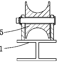
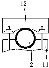
[0027] As shown in the figure, a long tube inside and outside suit tooling includes a base 1, a clamping device 4 for fixing a large tube 2 is arranged on the base 1, and a support device 5 for supporting a small tube 3, the small tube Several positioning posts 6 are arranged at intervals on the outer wall of 3 , and the height of the positioning posts 6 matches the designed gap between the small tube 3 and the large tube 2 . By setting the positioning post 6 on the outer wall of the small tube 3...


PUM


Abstract

The invention relates to a machining device, in particular to a tool for sleeving long tubes. The tool comprises a base; clamping devices used for fixing a large tube and supporting devices used for supporting a small tube are distributed on the base; a plurality of positioning posts are distributed on the outer wall of the small tube at intervals; the height of the positioning posts is equal to a designed gap between the small tube and the large tube. By providing the positioning posts on the outer wall of the small tube, the end of the small tube is avoided scratching the inner wall of the large tube; under supporting of the positioning posts, the gap between the small tube and the large tube can be precisely and uniformly controlled, and the problem that the middle of the small tube with the excess length bends, leading to peripheral non-uniformity of the gap between the small tube and the large tube, is avoided; meanwhile, the positioning posts between the large tube and the small tube support the tubes, after the small tube is completely nested in the large tube, strength and rigidity are greatly improved, and structural mechanical performances of the tube-in-tube structure can be improved.

Description

technical field [0001] The invention relates to the field of mechanical processing and manufacturing, in particular to a long tube inner and outer suit tooling. Background technique [0002] In the mechanical structure, the casing structure refers to the casing of a pipe with a smaller outer diameter and a pipe with a larger inner diameter. In the casing structure, the most important size requirements are not only the size of the pipe itself, but also the concentricity requirements between the pipes, especially in the field of precision instrument manufacturing, the concentricity between the pipes, and the inner wall of the large pipe. The precision of the gap between the outer walls of the tubules has become a controlling parameter for evaluating the good grade of this type of structure. [0003] In the current processing and manufacturing, it is usually to fix one of the pipes horizontally, then install the other pipe in alignment, and then fix the relative position after...

Claims


Application Information

Patent Timeline
IPC IPC(8): B23P19/04
CPCB23P19/04
Inventor 李文杰梅奇陈浩施川
Owner SICHUAN BLUSR MACHINERY
Learn More