
wet wall tower

A wetted wall tower and wetted wall column technology, applied in the field of gas capture equipment, can solve the problems of uneven gas distribution, high axial velocity, etc., and achieve the effects of reducing impact, eliminating volatility, and improving stability

Active Publication Date: 2016-09-28
CHINA PETROCHEMICAL CORP +2
View PDF3 Cites 0 Cited by
  • Summary
  • Abstract
  • Description
  • Claims
  • Application Information

AI Technical Summary

Problems solved by technology

Porous gas distributors are commonly used at present, but the axial velocity of the gas near the inlet is too high. Under the suction of the high-speed air flow, a recirculation zone is formed near the inlet, resulting in uneven gas distribution.

Method used


Image

  • wet wall tower
  • wet wall tower
  • wet wall tower

Examples


Embodiment Construction

[0059] The wetted wall column according to the present invention will be described in detail below with reference to the accompanying drawings.

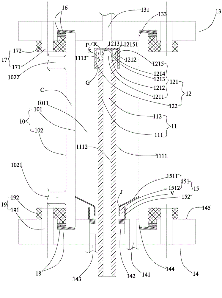
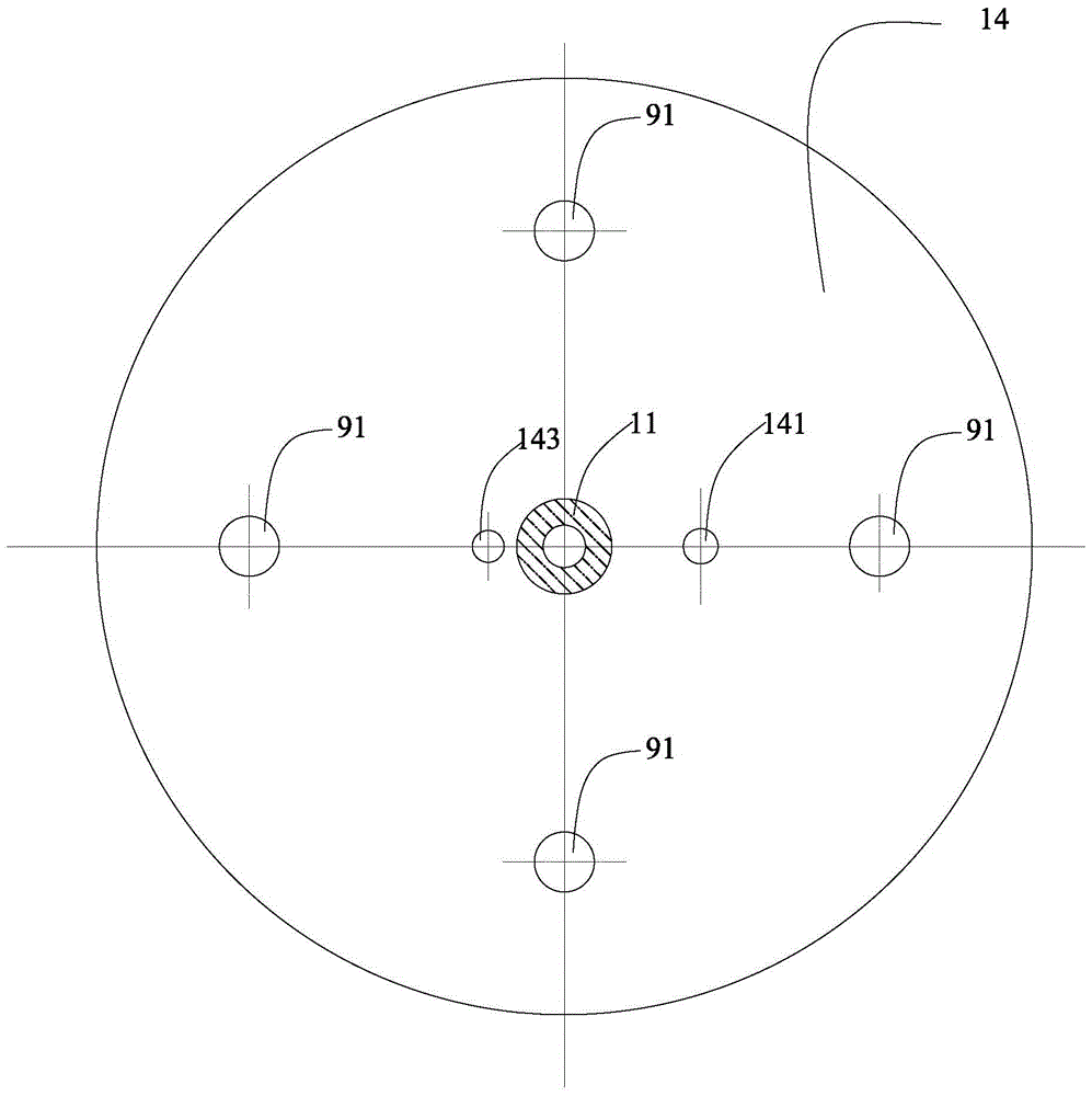
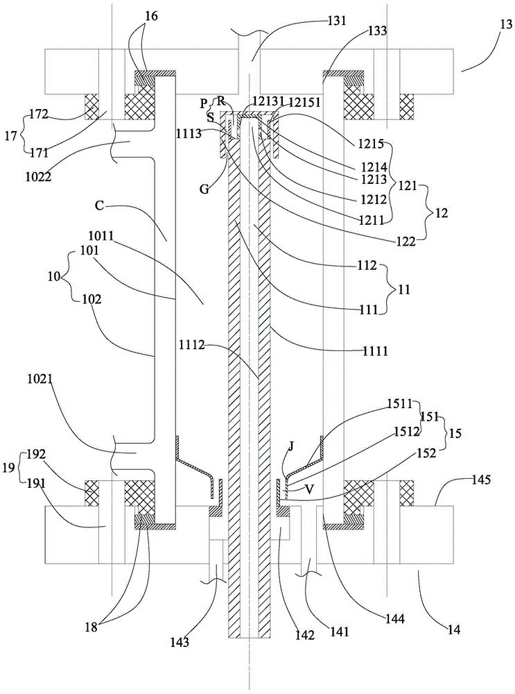
[0060] refer to Figure 1 to Figure 5 , The wetted wall column according to the present invention includes a jacket 10 , a wetted wall column 11 , a liquid distributor 12 , an upper flange 13 , a lower flange 14 and a gas distribution baffle 15 .

[0061] The jacket 10 has: an inner wall 101, which forms an accommodating cavity 1011; and an outer wall 102, which surrounds the inner wall 101 and forms a cavity C with the inner wall 101, and is provided with an insulating liquid inlet 1021 and an insulating liquid outlet 1022 communicating with the cavity C, The insulation fluid inlet 1021 , the cavity C and the insulation fluid outlet 1022 form a passage for the insulation fluid (not shown), and the insulation fluid flowing through the passage keeps the accommodating chamber 1011 insulated.

[0062] The wetted pilaster 11 is accommod...


PUM


Abstract

The invention provides a wetted wall tower. The wetted wall tower comprises a jacket, a wetted wall column, a liquid distributor, an upper flange, a lower flange and a gas distribution baffle, wherein the jacket is provided with an accommodating cavity; the wetted wall column is provided with a wall part and a hollow part; the upper flange is provided with a gas outlet; the lower flange is provided with a gas inlet, an annular groove and a liquid exhaust opening; the liquid distributor comprises an overflow body with overflow holes and a cap element which forms a liquid receiving cavity and a clearance; en external solution passes through a hollow part of the wetted wall column, the cavity of the overflow body, the liquid receiving cavity and the clearance and flows from top to bottom along the outer surface of the wall part of the wetted wall column so as to form a liquid membrane; an external gas enters from a gas inlet, and the flow direction of the external gas is adjusted by the gas distribution baffle, and the external gas is guided to the accommodating cavity of the jacket so as to be in contact with the liquid membrane in a counterflow mode, so that the gas is absorbed by the solution; the solution flowing from top to bottom along the outer surface of the wall part of the wetted wall column absorbs the gas, and then the gas is accumulated to the annular groove, and is exhausted out via the liquid exhaust opening as a waste liquid; the upward flowing gas containing the absorbed solution acts as exhausted gas, and is exhausted outward via the gas outlet.

Description

technical field [0001] The present invention relates generally to gas capture equipment, and more particularly to a wetted wall column. Background technique [0002] "Twelfth Five-Year" national science and technology support plan project "large-scale coal-fired power plant flue gas CO 2 Capture, flooding and storage technology (CCUS) development and application demonstration", capturing CO in power plant flue gas 2 Resources are supplied to oil fields for tertiary oil recovery. The purpose is to achieve CO 2 The dual goals of emission reduction and oilfield EOR flooding to stabilize production and increase income. In this context, the development of flue gas CO 2 Capture new technology and kinetic mass transfer characteristics research, guide large-scale carbon capture engineering process package design and engineering design, is beneficial to CO 2 The promotion of new technologies for emission reduction is of great significance to both ecological environmental protect...

Claims


Application Information

Patent Timeline
Patent Type & Authority Patents(China)
IPC IPC(8): B01D53/78B01D53/62B01D53/52B01D53/50B01D53/56
Inventor 陆诗建李清方张建陆胤君刘海丽尚明华张媛媛张启阳孙广领庞成志吴士雷
Owner CHINA PETROCHEMICAL CORP
Learn More