a primary filter

A primary filter and cylinder technology, applied in the field of primary filters, can solve the problems of reducing the service life of the filter, the impact of the filter, increasing the labor load of the staff, etc., and achieve the effect of increasing the service life and reducing the degree of metal fatigue.

Inactive Publication Date: 2016-08-24
东莞杰舜精密技术有限公司
View PDF4 Cites 0 Cited by
  • Summary
  • Abstract
  • Description
  • Claims
  • Application Information

AI Technical Summary

Problems solved by technology

The filter element assembly of the pass-through filter in the prior art basically includes two parts, namely the filter frame and the filter screen, which are welded by melting tin to form the filter element assembly. The filtration accuracy of the filter element assembly is 80 mesh. When the high-pressure liquid passes, the medium Containing tiny metal particles will enter the hydraulic system through the filter screen, causing pollution to the hydraulic valve and jack, reducing the service life of the valve and jack, and even malfunctioning due to the sealing failure of the hydraulic valve, resulting in personal and equipment accidents
[0003] And the traditional primary filtration for industrial oil usually uses ordinary filters to deal with large-diameter impurity particles in industrial oil, but during the injection process of industrial oil, the high-speed water flow has a greater impact on the filter. The large impact, and the impurity particles flowing at high speed will cause serious wear to the parts in the filter, which greatly reduces the service life of the filter. The solution adopted in the prior art is to directly adjust the industrial filter through the valve. The injection rate of the oil, but the mechanical valve needs to be manually adjusted continuously, which increases the labor load of the staff and greatly reduces the filtration efficiency of industrial oil

Method used


Image

  • a primary filter
  • a primary filter

Examples


Embodiment 1

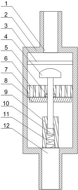
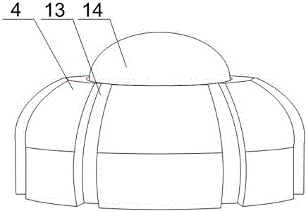
[0021] Such as figure 1 and figure 2 As shown, this embodiment includes a cylinder body 2 and an oil inlet 1 and an oil outlet 12 provided at the upper and lower ends of the cylinder body 2, and an isolation plate 7 is installed in the cylinder body 2, and the two ends of the isolation plate 7 There are a plurality of discharge holes 6, and also includes a support base 9 fixed in the cylinder body 2, a movable rod 10 is slidably arranged in the support base 9, a groove is provided at the lower end of the support base 9, and the lower end of the movable rod 10 passes through The spring 11 is connected to the bottom of the groove, the upper end of the movable rod 10 passes through the isolation plate 7 and a stopper 4 is fixed at its end, the stopper 4 is facing the oil inlet 1, and the stopper 4 includes a frustum-shaped body , a ball 14 is rotated on the top of the body, and a plurality of guide grooves 13 along the axis direction of the cylinder body 2 are annularly arrange...


PUM


Abstract

The invention discloses a primary filter, which comprises a barrel, wherein an isolating plate is arranged in the barrel; a plurality of drainage holes are formed in two ends of the isolating plate; a movable rod is arranged in a support base in a sliding manner; a groove is formed in the lower end of the support base; the lower end of the movable rod is connected with the bottom of the groove through a spring; the upper end of the movable rod penetrates through the isolating plate; a baffle block is fixedly arranged on the end part of the movable rod, and comprises a circular-truncated-cone-shaped body; a ball is rotationally arranged in the top end of the body; and a plurality of flow guide grooves are formed in the outer wall of the body in a ring. When the flow of industrial oil is reduced and the flow rate is retarded, the action stress on the spring is reduced; the spring restores certain deformation and then the movable rod pops upwards; the baffle plate does not contact the isolating plate again until injection of oil is stopped, so as to prevent the oil from being injected from the drainage holes; and flow control on the liquid in the barrel is achieved through up-and-down adjustment of the movable rod, so that the impact on the barrel caused by the oil is reduced, and the purpose of protecting the filter is achieved.

Description

technical field [0001] The invention relates to a filtering device, in particular to a primary filter. Background technique [0002] At present, the oil filter is widely used in the purification of hydraulic oil, hydraulic transmission oil, gear oil, gasoline engine oil, diesel engine oil, compressor oil, refrigeration oil and heat treatment oil, etc. The oil filter can quickly remove the moisture in the oil , gas and mechanical impurities, flash evaporation to remove light acids, light hydrocarbons, etc., thereby improving the quality of the oil, restoring the performance of the lubricating oil, and ensuring the normal operation of the power system, hydraulic system, and lubrication system. The filter element assembly of the pass-through filter in the prior art basically includes two parts, namely the filter frame and the filter screen, which are welded by melting tin to form the filter element assembly. The filtration accuracy of the filter element assembly is 80 mesh. Whe...

Claims


Application Information

Patent Timeline
Patent Type & Authority Patents(China)
IPC IPC(8): B01D29/03B01D29/90
Inventor 欧阳华宏
Owner 东莞杰舜精密技术有限公司
Why Eureka
Try Eureka