
Laser pen interaction method

An interactive method and laser pointer technology, applied in the field of human-computer interaction and computer vision, can solve the problems of misjudgment of interactive commands, easy misjudgment, image distortion, etc., and achieve the effect of solving background mutation

Active Publication Date: 2015-05-13
DALIAN UNIV OF TECH
View PDF9 Cites 10 Cited by
  • Summary
  • Abstract
  • Description
  • Claims
  • Application Information

AI Technical Summary

Problems solved by technology

[0003] Chinese patent 102262733 discloses a laser point detection method and device, which uses the camera to collect the state of the laser point for smooth drawing and other interactive functions. However, in the laser pointer interactive system, the background changes continuously due to functions such as slide page change, and the system cannot Robust detection of laser points; Chinese patent 103116889 discloses a positioning method and electronic equipment, which uses linear transformation to complete the coordinate mapping module. However, due to the placement of the camera, image acquisition, and projection, image distortion may occur, and linear changes cannot Reach the accuracy required by the system; U.S. Patent 20040239653 discloses an interactive indicating device that interacts by identifying the state of the laser point. However, the system uses the laser point to flicker and is prone to misjudgment of interactive commands, and the realization of drawing annotations in the interactive method is easy to misjudgment
The existing patented technology of laser pen interaction still does not solve the problem of laser point detection with background changes, the problem of nonlinear distortion of coordinate mapping, and the problem of misjudgment of interactive commands prone to interactive methods

Method used


Image

  • Laser pen interaction method
  • Laser pen interaction method
  • Laser pen interaction method

Examples


Embodiment Construction

[0070] Embodiment of the present invention is described in detail below in conjunction with accompanying drawing: present embodiment implements under the premise of the technology of the present invention, has provided detailed embodiment and specific operation process, but protection scope of the present invention is not limited to following implementation plan.

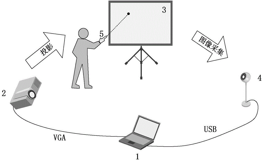
[0071] The system block diagram of the present invention is as figure 1 As shown, it is composed of a computer 1, a projector 2, a projection screen 3, a camera 4 and a laser pointer 5. The computer 1 and the projector 2 are connected through VGA to project the computer content to the projection screen 3, and the camera 4 is placed in a place capable of collecting all projections. screen content, the collected image is sent back to the computer 1 via USB, and then the computer 1 completes the laser pointer interaction method.

[0072] The implementation process of the interactive method is as follows figure 2 As ...


PUM


Abstract

The invention discloses a laser pen interaction method which resolves the problems of laser point wrong detection, large coordinate mapping errors and wrong judgment of interaction instructions in the background switching process of a laser pen interaction system in the prior art. The laser pen interaction method includes a self-adaptive background switching laser point detection method, a non-linear coordinate mapping method and a regional interaction method. An on-line background dictionary building and updating method and a spare reconstruction method detect out a movable laser point in a real-time robust mode, and the problem of background sudden changing caused by a page changing or drawing function of slides in the interaction process can be well resolved. A coordinate mapping coefficient is trained through a nerve network study model, and the coordinate mapping accuracy is improved. By dividing a projection screen into a drawing interaction area and a control interaction area, the problem of wrong judgment of interaction instructions is resolved. The laser pen interaction method can finish the laser pen interaction function in a real-time robust mode, and can be widely applied to a multimedia demonstration system in conferences, speeches, teaching and the like.

Description

technical field [0001] The invention belongs to the field of human-computer interaction and computer vision, and more specifically relates to a laser point detection method, a coordinate mapping method and an interaction method in a laser pen interaction system. Background technique [0002] Today, laser pointers have been widely used in multimedia presentation systems such as conferences, speeches, and teaching. With the help of laser pointers, speakers can leave the computer and manipulate speeches, so that they can interact with the audience more commonly to complete the task of information transmission. However, there are still many defects in the existing laser pointer interactive system. For example, Chinese patent 03270412 discloses a laser pointer with a page-turning button and a wireless transceiver. However, the function is relatively single, which cannot meet the needs of the speaker; Chinese patent 102073395 discloses a wireless laser pointer interactive system b...

Claims


Application Information

Patent Timeline
Patent Type & Authority Applications(China)
IPC IPC(8): G06F3/0354G06F3/0487
CPCG06F3/038G06F3/0386
Inventor 金明录王志华郝育闻
Owner DALIAN UNIV OF TECH
Learn More