
Internet based indoor condensation detection system and method

A detection system and Internet technology, applied in signal transmission systems, electrical signal transmission systems, measuring devices, etc., can solve the problems that data collection can only be carried out on site, cannot realize long-distance data transmission, and cannot meet continuous real-time detection, etc. , to achieve the effects of long-term real-time detection, strong adaptability to climate and environment, and short test time

Inactive Publication Date: 2015-05-13
上海市房地产科学研究院
View PDF6 Cites 2 Cited by
  • Summary
  • Abstract
  • Description
  • Claims
  • Application Information

AI Technical Summary

Problems solved by technology

This method has the following disadvantages: first, each measurement must go to the site to arrange a measuring instrument, and then dismantle the measuring instrument after the measurement is completed, the workload is heavy and repetitive; second, only the data of the environment at that time can be recorded. It cannot meet the requirements of continuous real-time detection; thirdly, data collection can only be carried out on site, and long-distance data transmission cannot be realized, which is limited by objective factors such as weather and personnel

Method used


Image

  • Internet based indoor condensation detection system and method
  • Internet based indoor condensation detection system and method

Examples


Embodiment Construction

[0039] The following describes the Internet-based indoor condensation detection system and method of the present invention in further detail with reference to the accompanying drawings and specific embodiments, but the protection scope of the present invention should not be limited by this.

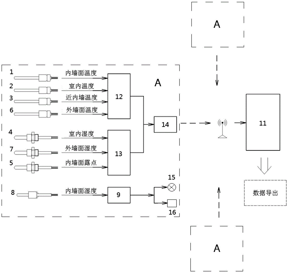
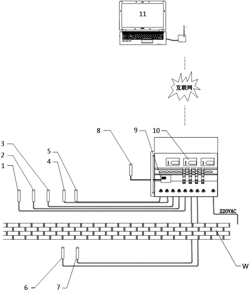
[0040] Please refer to figure 1 with figure 2 The Internet-based indoor condensation detection system includes a host computer 11 located in the monitoring center and a number of indoor condensation detectors A arranged at the test site of the house. In this embodiment, there are three indoor condensation detectors A; The indoor condensation detector A detects the measured wall W at each site separately, and collects the internal wall temperature, indoor ambient temperature, indoor near-wall temperature, external wall temperature, indoor environmental humidity, and external wall humidity. The data on the humidity of the inner wall and the dew point of the wall are then transmitted to the ho...


PUM


Abstract

Discloses is an Internet based indoor condensation detection system and method. The Internet based indoor condensation detection system comprises an upper computer and a plurality of indoor condensation detectors, wherein the upper computer is located in a monitoring center and the plurality of indoor condensation detectors are arranged on building test sites respectively. The detection is performed on a detected wall body of every site through the corresponding indoor condensation detector, data of the inner wall surface temperature, the indoor environment temperature, the indoor close-to-wall position temperature, the outer wall surface temperature, the indoor environment humidity, the outer wall surface humidity, the inner wall surface humidity and wall body dew points are collected to be timely transmitted to the upper computer through the Internet for data display, recording and storage, the data analysis is performed to obtain the indoor condensation coefficient of every detected wall body, and meanwhile the site alarm is performed on the condensation of every detected wall body according to a detection result through the corresponding indoor condensation detector. According to the Internet based indoor condensation detection system and method, the remote transmission of the measurement data, the networking monitoring of the plurality of sites and the site alarm formed by the condensation are implemented, the adaptability to the environment is high, the test time is short, the measurement accuracy is high, the detection cost is low, the stability is high, the use is convenient, and the Internet based indoor condensation detection system and method is particularly suitable for the real-time collection on the continuous data of the plurality of unmanned sites.

Description

Technical field [0001] The invention relates to the detection of a house structure environment, in particular to an indoor condensation detection system and method based on the Internet, and belongs to the field of construction technology. Background technique [0002] In daily life, we can see that when the air temperature at night decreases, a part of the moisture in the air will be analyzed to form dew or frost. This is because the air in nature contains a certain amount of water vapor. Under certain pressure conditions, the water vapor in the air is related to temperature. The higher the temperature, the more water vapor it can hold. But for every temperature, there is a saturation value. When this saturation value is exceeded, water vapor will condense and become liquid water. The temperature corresponding to this saturation value, that is, the temperature at which water vapor in the air begins to condense, is called the dew point temperature, or "dew point". The relations...

Claims


Application Information

Patent Timeline
IPC IPC(8): G01D21/02G08C19/00G08C17/02
Inventor 赵鸿周云许利军王俊伟陈志强宋平朱萍
Owner 上海市房地产科学研究院
Learn More