
Material feeding mechanism for 3D printer

A 3D printer and feeding mechanism technology, applied in the direction of additive processing, etc., can solve the problems of affecting the stability of wire feeding and printing accuracy, inconvenient adjustment of wire feeding pressing force, and affecting the quality of printed products, so as to improve the feeding Wire reliability, increased transmission reliability, and compact structure

Inactive Publication Date: 2015-05-13
UNIV OF JINAN
View PDF8 Cites 2 Cited by
  • Summary
  • Abstract
  • Description
  • Claims
  • Application Information

AI Technical Summary

Problems solved by technology

[0002] The material feeding mechanism of the 3D printer in the prior art is generally set on the upper support of the printer, or connected to the upper support plate through the support frame. The tight force makes the stability of wire feeding poor, and even affects the quality of printed products. At the same time, due to the heavy weight of the wire feeding and printing mechanism including the motor, the output shaft of the motor and the wire feeding structure are easily deformed and vibrated after being stressed. It also affects the stability of wire feeding and the accuracy of printing

Method used


Image

  • Material feeding mechanism for 3D printer
  • Material feeding mechanism for 3D printer
  • Material feeding mechanism for 3D printer

Examples


Embodiment Construction

[0023] In order to better understand the present invention, the implementation manner of the present invention will be explained in detail below in conjunction with the accompanying drawings.

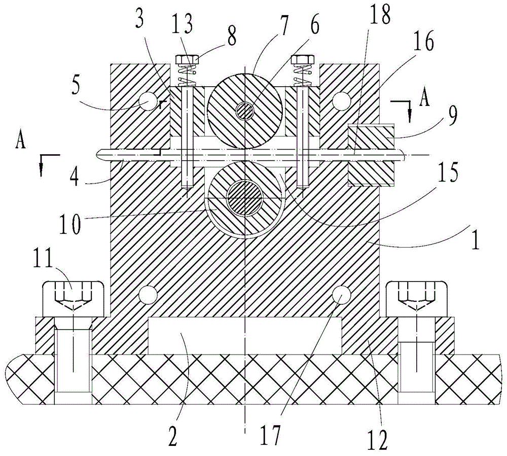
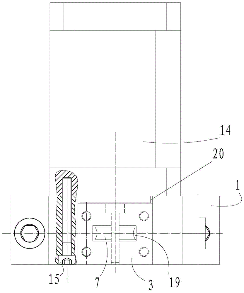
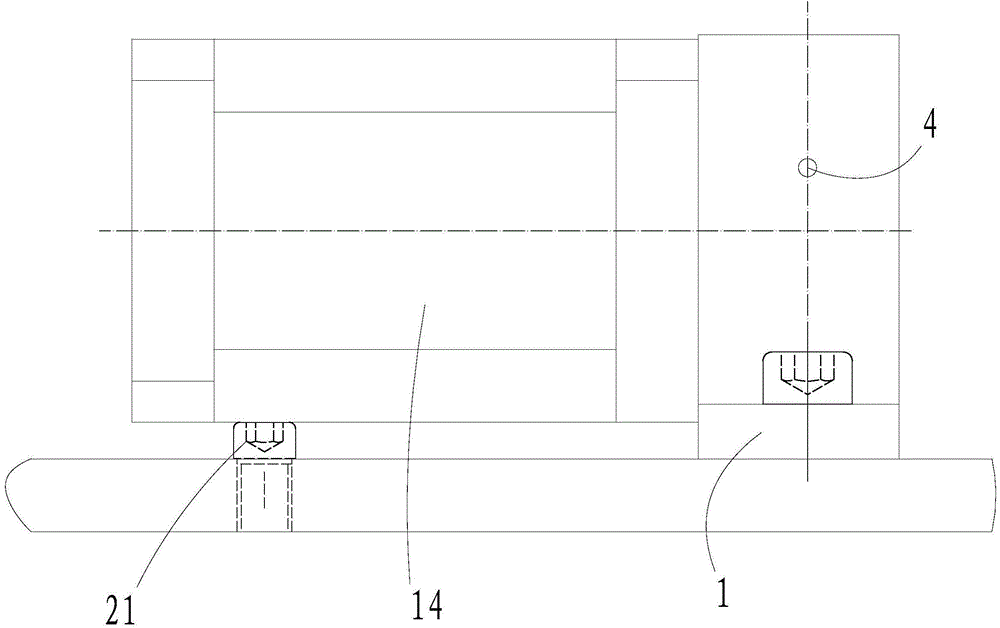
[0024] like Figure 1 to Figure 4 As shown, a 3D printer material feeding mechanism includes a stepping motor 14, the stepping motor is connected to the motor bracket 1, the upper part of the motor bracket 1 is connected to the fixed platen 3, and the motor bracket is connected to the connecting plate on the printer. The middle of the motor bracket is provided with a U-shaped groove 15, and the horizontal end faces on both sides of the groove mouth are provided with vertical bracket threaded holes, and upward bosses 16 are provided on both sides of the horizontal end face, and the bosses are provided with motor upper connection. The hole 5 is provided with the lower connection hole 17 of the motor at the bottom of the motor bracket, and the output shaft of the stepping motor 14 is provi...


PUM


Abstract

The invention discloses a material feeding mechanism for a 3D printer. The material feeding mechanism comprises a stepping motor, wherein the stepping motor is connected with a motor bracket, the upper part of the motor bracket is connected with a fixed pressure plate, the motor bracket is connected with an upper connecting plate of the printer, a U-shaped groove is formed in the motor bracket, bracket screw holes are formed in the two sides of the mouth of the groove respectively, bosses are formed in the two sides of a horizontal end surface respectively, a motor connecting hole is formed in each boss, a wire feeding driving wheel is arranged on an output shaft of the stepping motor, a wire inlet and a wire outlet which are vertical to the axial line of the U-shaped groove are formed in each boss, a rectangular groove hole is formed in the middle of the fixed pressure plate, wire feeding wheel connecting holes are formed in the two side walls of the rectangular groove hole respectively and provided with wire feeding wheel fixed shafts respectively, and a wire feeding wheel is arranged on each wire feeding wheel fixed shaft and in the rectangular groove hole and is matched with the wire feeding driving wheel to finish feeding of a printing wire. The material feeding mechanism has a compact structure, is light in quality, good in rigidity, convenient to assemble and disassemble and less prone to deformation and is capable of ensuring reliable feeding of the printing wire and the quality of a printed product.

Description

technical field [0001] The invention relates to the technical field of 3D printers, in particular to a 3D printer material feeding mechanism. Background technique [0002] The material feeding mechanism of the 3D printer in the prior art is generally set on the upper support of the printer, or connected to the upper support plate through the support frame. The tight force makes the stability of wire feeding poor, and even affects the quality of printed products. At the same time, due to the heavy weight of the wire feeding and printing mechanism including the motor, the output shaft of the motor and the wire feeding structure are easily deformed and vibrated after being stressed. It also affects the stability of wire feeding and the accuracy of printing. Contents of the invention [0003] The purpose of the present invention is to provide a 3D printer material feeding mechanism to solve the above-mentioned problems in the prior art; A reliable supply to ensure the qualit...

Claims


Application Information

Patent Timeline
IPC IPC(8): B29C67/00B33Y40/00
Inventor 隗德民
Owner UNIV OF JINAN
Learn More