Automatic paint sprayer for spraying outer wall of wind power tower
A technology for automatic paint spraying machines and wind power towers, which is applied in spraying devices, liquid spraying devices, coatings, etc., and can solve problems such as waste of paint, poor working environment for workers, and low work efficiency
- Summary
- Abstract
- Description
- Claims
- Application Information
AI Technical Summary
Problems solved by technology
Method used
Image
Examples
specific Embodiment approach 1
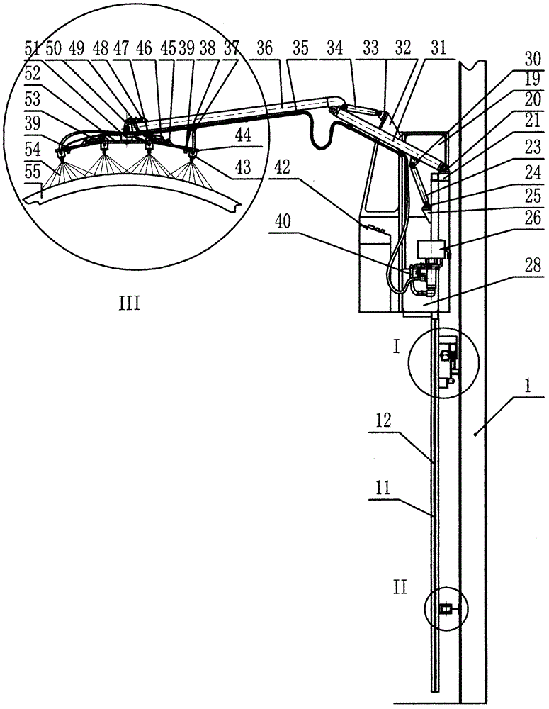
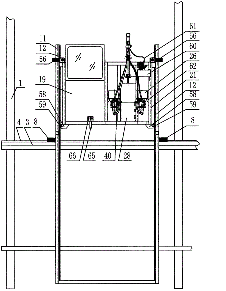
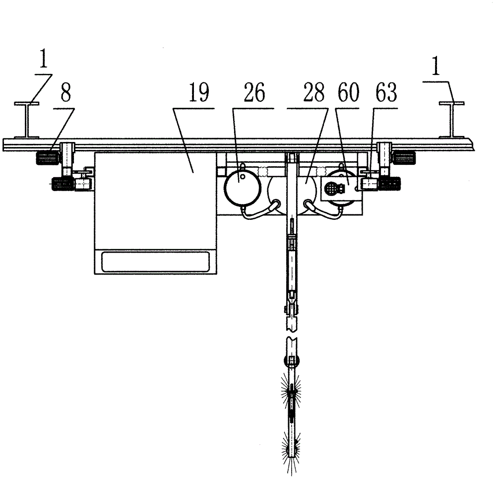
[0011] Specific embodiment 1, combination figure 1 , figure 2 , image 3 , Figure 4 , Figure 5 , Image 6 Describe this embodiment. This embodiment consists of I-beam 2, walking motor reducer 8, frame 21, airless sprayer 26, rear extension arm 31, front extension arm 36, spray gun 43, control room 19, and electric control cabinet 42. Lift motor 56, hydraulic pump station 60, limit wheel 17, lift rack 12, rack mount 11, balance adjustment cylinder 49, swing motor 51, nozzle adjustment cylinder 46, nozzle distance detection device 39, paint tube 37 , Spray gun fixing frame 44, hydraulic oil pipe 61, paint suction pipe 40, paint storage bucket 28, air filter 66, positioning gear 59, rolling guide 3, characterized in that the spray booth wall column 1 is welded with I-beam 2, The rolling guide 3 is fixed on the I-beam 2, the angle steel 4 is welded to the rolling guide 3, the roller 5 is placed on the angle steel 4, and it is driven by the walking motor reducer 8. The roller 5 i...
specific Embodiment approach 2
[0012] Specific embodiment 2, combined figure 1 , figure 2 , image 3 , Image 6 Describe this embodiment, this embodiment is that there are multiple airless spraying machines 26, multiple airless spraying machines 26 are fixed on the frame 21, the outlet of the airless spraying machine 26 is connected with the paint tube 37, the paint tube 37 The other end is connected with multiple sets of spray guns 43. The spray gun 43 is fixed on the spray gun holder 44. The distance between the spray gun 43 and the workpiece 55 is detected by the nozzle distance detection device 39, the nozzle adjustment cylinder 46 performs distance adjustment, and the swing motor 51 controls The rotation angle of the spray gun assembly frame 52 and the level of the spray gun assembly frame 52 are completed by the parallel adjustment cylinder 49. The inlet of the airless sprayer 26 is connected to the paint suction pipe 40, and the other end of the paint suction pipe 40 is placed in the oil storage barre...
specific Embodiment approach 3
[0013] Specific embodiment 3, combined figure 1 , figure 2 , image 3 , Figure 4 , Figure 5 Describe this embodiment, this embodiment is that the lifting motor 56 is fixed on the frame 21, through the lifting gear 63 and the lifting rack 12 want to mesh, the frame 21 is raised to the required height, and the traveling motor reducer 8 and roller 5 Connected, the roller 5 is placed on the angle steel 4, the angle steel 4 is welded to the rolling guide 3, the rolling guide 3 is fixed to the I-beam 2, the roller 5 is fixed on the support frame 6, and the support frame 6 is fixed on the horizontal tube 7. , The horizontal tube 7 is connected with the rack fixing frame, and the entire frame 21 moves on the rolling guide 3 under the driving of the walking motor reducer 8. At this time, the upper and lower positioning wheels 14 position the frame 21 in the up and down direction, thereby Realize the rising and moving of the rack.
PUM
 Abstract
Description
Claims
Application Information
 - R&D Engineer
- R&D Manager
- IP Professional
- Industry Leading Data Capabilities
- Powerful AI technology
- Patent DNA Extraction
Browse by: Latest US Patents, China's latest patents, Technical Efficacy Thesaurus, Application Domain, Technology Topic, Popular Technical Reports.
© 2024 PatSnap. All rights reserved.Legal|Privacy policy|Modern Slavery Act Transparency Statement|Sitemap|About US| Contact US: help@patsnap.com


