
Multifunctional fluid mechanics experimental device

A technology of fluid mechanics and experimental equipment, applied in teaching models, educational tools, instruments, etc., can solve problems such as inconvenient disassembly and installation, leakage of water and pressure pipe sections, damage, etc., to avoid high-frequency disassembly and assembly, easy to assemble and move, extend The effect of service life

Inactive Publication Date: 2015-05-06
JIANGSU POLYTECHNIC COLLEGE OF AGRI & FORESTRY
View PDF9 Cites 17 Cited by
  • Summary
  • Abstract
  • Description
  • Claims
  • Application Information

AI Technical Summary

Problems solved by technology

[0002] Existing fluid mechanics experimental devices or experimental pipelines are scattered, and a set of experimental devices can only conduct one kind of fluid mechanics principle test. When performing other tests, it is necessary to disassemble the test pipe section and then install the corresponding test pipe section, because most of the test pipe sections are made of glass products. , It is extremely inconvenient to disassemble and install, and it is easy to cause water leakage and pressure leakage or damage to the pipe section. The entire replacement process is cumbersome, time-consuming and laborious
There are many experimental pipelines, and it is easy for students to be confused when disassembling and replacing them, which will affect the experimental results and students' understanding of the principles

Method used


Image

  • Multifunctional fluid mechanics experimental device
  • Multifunctional fluid mechanics experimental device

Examples


Embodiment Construction

[0020] The present invention will be further described in detail below in conjunction with the accompanying drawings.

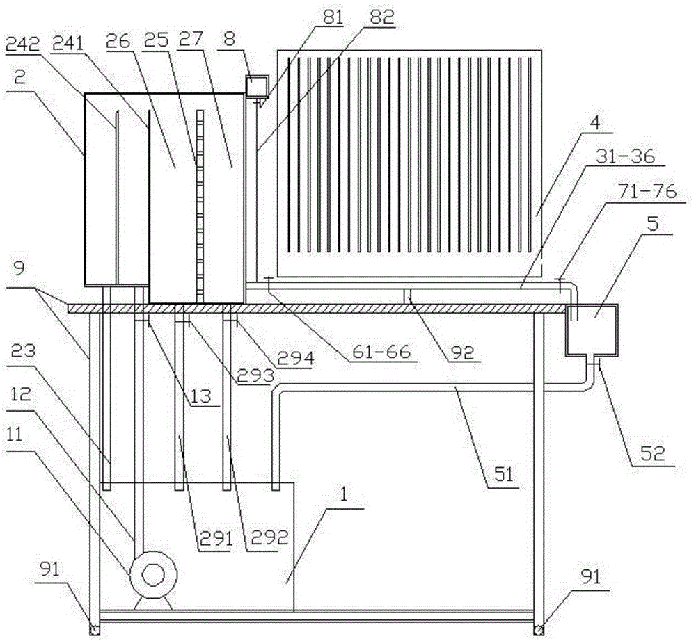
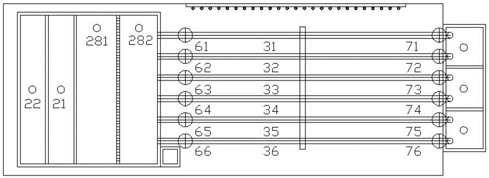
[0021] Such as figure 1 , figure 2 As shown, the test bench 9 is a stainless steel structure as a whole, and the universal wheels 91 are mounted on the bottom to facilitate movement. A water storage tank 1 is fixed on the lower left side of the test stand 9, and a water pump 11 is installed inside. Water is sent to the experimental water tank through the water supply pipe 12 by the water pump 11, and the water supply flow can be regulated by the water supply valve 13. After water enters the test water tank 2, it first passes through the triangular weir 241, and then flows out through the orifice plate 25. When the water flow rises to a certain height, the water flow enters the overflow area through the overflow weir 242, and the overflow water returns to the water storage tank 1 through the overflow pipe 23. A drainage pipe 291,292 is respectively set in t...


PUM


Abstract

The invention discloses a multifunctional fluid mechanics experimental device. The multifunctional fluid mechanics experimental device comprises a water source, a reynolds experiment pipe, a Bernoulli experiment pipe, an on-way resistance pipe, a local resistance pipe, a valve local resistance measuring pipe, a pitot pipe, a Venturi meter, an orifice plate flowmeter, a piezometer pipe, a measuring groove, selection valves and adjusting valves; the reynolds experiment pipe, the Bernoulli experiment pipe, the on-way resistance pipe, the local resistance pipe, the valve local resistance measuring pipe, the Bernoulli experiment pipe, the venture meter and the orifice plate flowmeter form into six testing pipe sections in a parallel mode; the selection valves are installed at inlet sections of the experiment pipe sections; the inlet sections of the experiment pipe sections are connected with a water source through the selection valves; the adjusting valves are installed at outlet sections of the experiment pipes; the outlet sections of the experiment pipes are connected with the measuring groove through the adjusting valves. According to the multifunctional fluid mechanics experimental device, the separated experiment pipelines are integrated in one experiment device, frequent assembling and disassembling is avoided, leakage is reduced, the experiment pipelines are clear at a glance and not easy to mix, and user understanding of the experimental principle is facilitated.

Description

technical field [0001] The invention belongs to the field of test instruments, in particular to a multifunctional fluid mechanics test device. Background technique [0002] Existing fluid mechanics experimental devices or experimental pipelines are scattered, and a set of experimental devices can only conduct one kind of fluid mechanics principle test. When performing other tests, it is necessary to disassemble the test pipe section and then install the corresponding test pipe section, because most of the test pipe sections are made of glass products. , It is extremely inconvenient to disassemble and install, and it is easy to cause water leakage and pressure leakage or damage to the pipe section. The entire replacement process is cumbersome, time-consuming and laborious. There are many experimental pipelines, and it is easy for students to be confused when disassembling and replacing them, which will affect the experimental results and students' understanding of various pri...

Claims


Application Information

Patent Timeline
Patent Type & Authority Applications(China)
IPC IPC(8): G09B23/12
CPCG09B23/12
Inventor 陆建兰刘建华
Owner JIANGSU POLYTECHNIC COLLEGE OF AGRI & FORESTRY
Learn More