A built-in oil separator type condenser

A technology of oil separator and condenser, which is applied in the direction of evaporator/condenser, refrigerator, refrigeration components, etc., can solve the problem of increasing difficulty in processing and manufacturing refrigeration oil filling equipment, increasing the size of refrigeration and air-conditioning units, and product market competition Reduce the force weakening and other problems, to achieve the effect of reducing external leakage points, reducing heat transfer dead angle, and reducing welding processing workload

Active Publication Date: 2017-02-22
MCQUAY AIR CONDITIONING & REFRIGERATION WUHAN
View PDF10 Cites 0 Cited by
  • Summary
  • Abstract
  • Description
  • Claims
  • Application Information

AI Technical Summary

Problems solved by technology

For the entire refrigerating and air-conditioning unit, the pursuit of higher refrigeration oil separation efficiency means increasing the specification of the external oil separator, which in turn increases the overall size of the refrigerating and air-conditioning unit, requiring larger installation and operating space , also caused an increase in the amount of refrigerated oil and the difficulty of equipment processing and manufacturing, which will inevitably bring about a cost disadvantage and weaken the market competitiveness of the product

Method used


Image

  • A built-in oil separator type condenser
  • A built-in oil separator type condenser
  • A built-in oil separator type condenser

Examples


Embodiment Construction

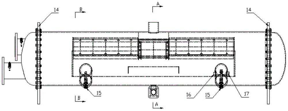
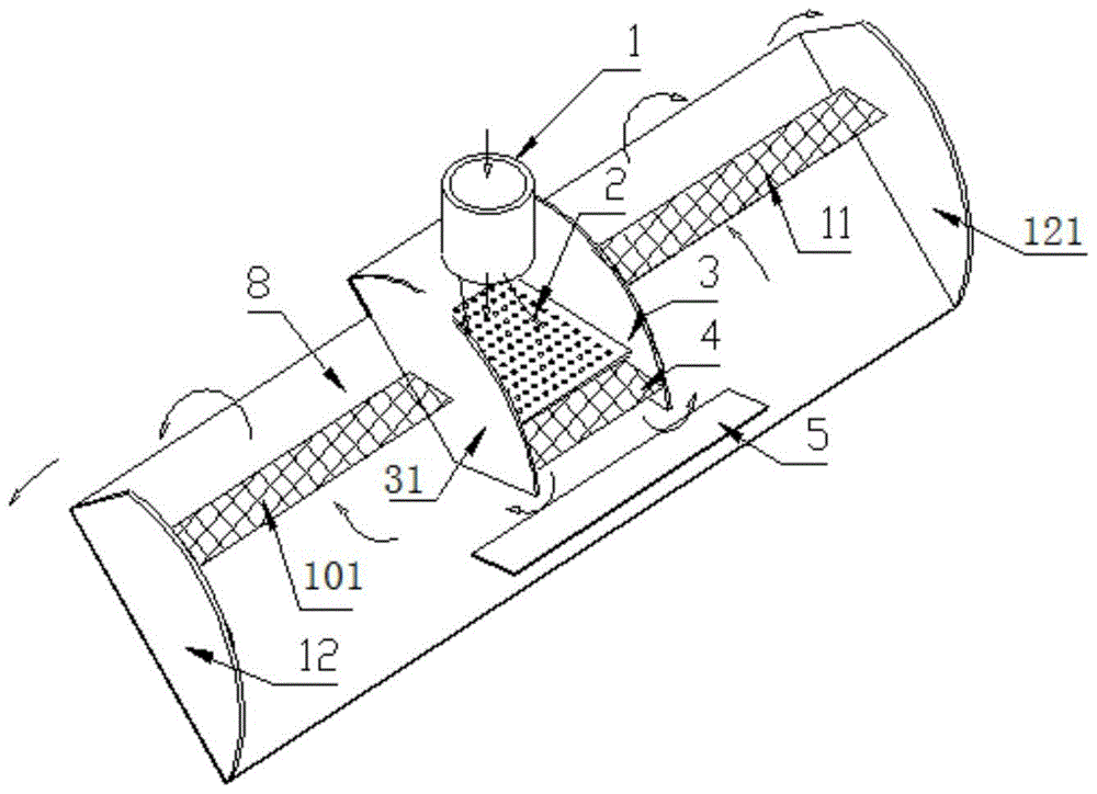
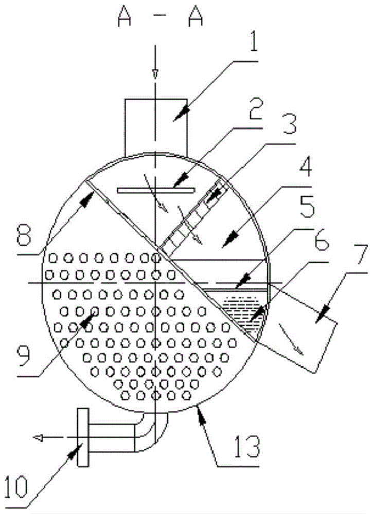
[0016] Attached below figure 1 , 2 , 3, 4 and embodiment further illustrate the utility model:

[0017] This embodiment is a built-in oil separator condenser used in a refrigeration and air-conditioning unit with a heat load of 690KW and a model of C2209. It includes an air intake pipe 1, a built-in oil group, an oil collection pipe group 7, and a condensing heat exchange pipe group. 9. Liquid outlet pipe group 10, condenser cylinder 13, and tube plate 14, first connect the air inlet pipe 1, liquid outlet pipe group 10, and oil collecting pipe 7 according to figure 1 Assemble with the condenser cylinder 13, wherein the built-in oil group is composed of the gas baffle 2, the first baffle 3, the second baffle 31, the third baffle 5, the fourth baffle 12, the fifth baffle 121, The first stainless steel filter screen group 4, the second stainless steel filter screen group 11, the third stainless steel filter screen group 101, and the convex partition 8 are composed of figure 2...


PUM


Abstract

The invention provides a condenser with a built-in oil separator. The condenser has the advantages that the structure is simple, the processing and manufacturing cost is low, and the like. The condenser with the built-in oil separator adopts a built-in oil separation assembly, the oil separator and the condenser are effectively and structurally integrated, a pressure container casing of one set of oil separator is omitted, the appearance dimension of an air conditioner refrigerating unit is greatly reduced, about 50 percent of welding processing workload is reduced, and possibly existing external leaking points of a system are further and greatly reduced. Through the adoption of a combined design of an air blocking plate and a third baffle plate, the flow rate of mixed gas entering the built-in oil separation assembly is effectively decelerated, so that the mixing gas is more uniform when passing through the filtering net plate group, the oil separation capability of the built-in oil separation assembly is effectively improved, meanwhile, a two-stage two-way filtering net oil separation structure is adopted, higher reliability is realized through being compared with that of a traditional built-in oil separator, and the oil separation efficiency can reach higher than 99.9 percent. Through the adoption of the designs of a convex separation plate, a fourth baffle plate and a fifth baffle plate, the heat exchange dead corner caused by the design of the built-in oil separator is greatly reduced. Compared with the traditional condenser with the built-in oil separator, the condenser provided by the embodiment of the invention has the advantages that the heat exchange efficiency is higher, and further, a higher energy efficiency ratio is obtained.

Description

technical field [0001] The invention relates to a condenser used in a refrigeration and air-conditioning system, in particular to a condenser with a built-in oil separator. Background technique [0002] The main components of the refrigeration and air conditioning system are composed of refrigeration compressors, oil separators, condensers, expansion throttling devices, evaporators and power control systems. Among them, the refrigeration oil mainly plays the role of lubricating and cooling the moving parts in the system. In the case of a certain filling amount, more refrigeration oil enters the condenser and evaporator, which will not only cause oil shortage in the oil supply system and increase the movement of the compressor The possibility of parts being burned due to lack of oil, and too much refrigerated oil will adhere to the heat exchange tubes in a film state, causing the heat exchange effect of the entire unit to fail to reach the design state. Refrigeration and air...

Claims


Application Information

Patent Timeline
Patent Type & Authority Patents(China)
IPC IPC(8): F25B39/04F25B43/02
CPCF25B39/04F25B43/02F25B2339/04
Inventor 徐峰解金海朱海晶王晓果黄海
Owner MCQUAY AIR CONDITIONING & REFRIGERATION WUHAN
Why Eureka
Try Eureka