
Variable compression ratio apparatus

一种压缩比、可变的技术,应用在发动机控制、机器/发动机、机械设备等方向,能够解决难以实现可变压缩比装置快速响应性、降低电动机容量等问题

Active Publication Date: 2015-05-06
HYUNDAI MOTOR CO LTD
View PDF7 Cites 6 Cited by
  • Summary
  • Abstract
  • Description
  • Claims
  • Application Information

AI Technical Summary

Problems solved by technology

Therefore, the limitation is that the capacity of the motor is reduced
At the same time, if the mechanical components are complicatedly connected, it is difficult to realize the quick response of the variable compression ratio device

Method used


Image

  • Variable compression ratio apparatus
  • Variable compression ratio apparatus
  • Variable compression ratio apparatus

Examples


Embodiment Construction

[0040] Reference will now be made in detail to various embodiments of the invention, examples of which are illustrated in the accompanying drawings and described below. While the invention will be described in conjunction with exemplary embodiments, it will be appreciated that present description is not intended to limit the invention to those exemplary embodiments. On the contrary, the invention is intended to cover not only the exemplary embodiments, but also various alternatives, modifications, equivalents and other embodiments, which may be included within the spirit and scope of the invention as defined by the appended claims .

[0041] Exemplary embodiments of the present invention will be described in detail below with reference to the accompanying drawings.

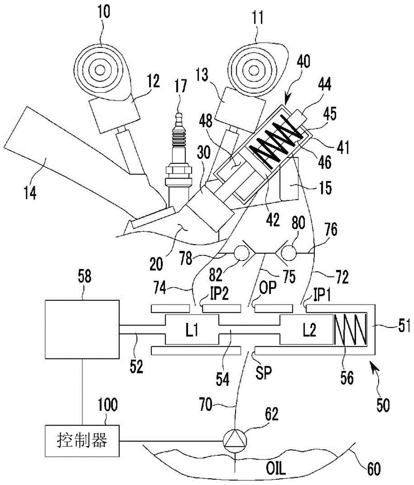
[0042] figure 1 is a schematic diagram of a variable compression ratio device according to an exemplary embodiment of the present invention.

[0043] Such as figure 1 As shown, the variable compression ratio d...


PUM


Abstract

A variable compression ratio apparatus may include an operating unit operated by hydraulic pressure to reciprocate the plunger, an oil control valve controlling hydraulic pressure supplied to the operating unit, an oil supplying unit storing oil supplied to the operating unit via the oil control valve and transmitting the stored oil to the oil control valve, an actuator operating the oil control valve, and a controller connected with the actuator to control the actuator according to an operational state of an engine.

Description

[0001] Cross References to Related Applications [0002] This application claims priority and benefit from Korean Patent Application No. 10-2013-0129966 filed on Oct. 30, 2013, the entire contents of which are hereby incorporated by reference for all purposes. technical field [0003] The invention relates to a variable compression ratio device. More specifically, the present invention relates to a variable compression ratio device that changes the volume of a combustion chamber, thereby changing the compression ratio. Background technique [0004] Generally, the thermal efficiency of a heat engine increases when the compression ratio is higher. Here, the compression ratio is the ratio of the volume of gas flowing to the cylinder and compressed by the piston, and is represented by "cylinder volume at top dead center of piston / combustion chamber volume". That is, as the top dead center of the piston becomes higher, the compression ratio increases. [0005] In the case of a...

Claims


Application Information

Patent Timeline
Patent Type & Authority Applications(China)
IPC IPC(8): F02D15/04
CPCF02B75/042F02D15/04F02B75/04F02D15/02
Inventor 金远圭崔命植
Owner HYUNDAI MOTOR CO LTD
Learn More