Hydraulic support linkage self-moving device and hydraulic support linkage self-moving method

A hydraulic support and self-moving technology, which is applied to the mine roof support, earth square drilling, mining equipment, etc., can solve the problems of cumbersome construction process, offset and dislocation of three hydraulic supports, unable to maintain the empty roof area, etc., to eliminate Injury to people due to broken connectors and broken wire ropes, improved removal speed and support efficiency, construction safety, rapid removal and roof support effects

Inactive Publication Date: 2015-05-06
枣庄矿业(集团)有限责任公司柴里煤矿
View PDF7 Cites 3 Cited by
  • Summary
  • Abstract
  • Description
  • Claims
  • Application Information

AI Technical Summary

Problems solved by technology

The use of the back column winch for traction still has serious problems such as misalignment of traction, long ropes, and excessive impact force of floating ropes. Traction can only be pulled by force, which can easily cause damage to connectors and injuries to people due to broken wire ropes.
Due to the misalignment of the traction, the offset and misalignment of the three hydraulic supports are often caused. The three hydraulic supports must be adjusted separately with the column return machine. This method is labor-intensive and time-consuming.
Using the back column winch to pull the three hydraulic supports, it is inevitable that when the removal fr...

Method used


Image

  • Hydraulic support linkage self-moving device and hydraulic support linkage self-moving method
  • Hydraulic support linkage self-moving device and hydraulic support linkage self-moving method

Examples


Embodiment Construction

[0017] The present invention will be further described below in conjunction with accompanying drawing and specific embodiment:

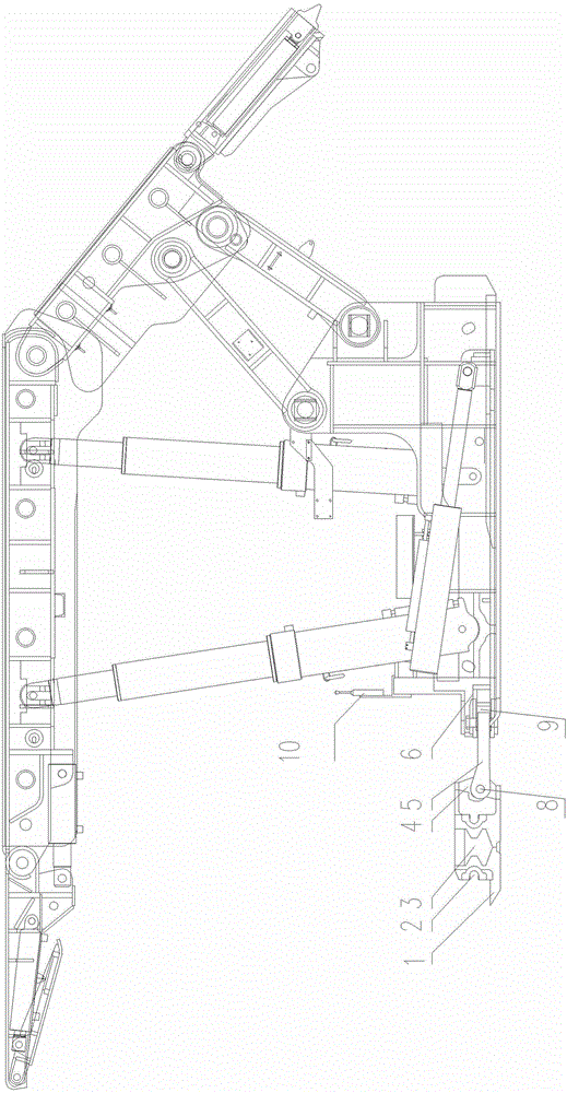
[0018] The present invention as figure 1 as shown,

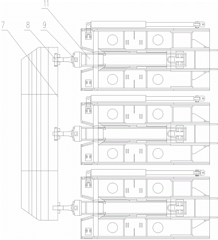
[0019] A hydraulic support combined self-moving device, including a hydraulic support 6 with a horizontal hydraulic push rod 5 and a control valve group, characterized in that the hydraulic support 6 is three groups of hydraulic support a, hydraulic support b and hydraulic support c. It also includes a cross bar 3 and a push rod 5. The front end of the cross bar 3 is provided with a shovel plate 1, and the rear end of the cross bar 3 is provided with a pin lug 4 to connect three groups of uniformly distributed push rods 5 through the pin shaft a8. The push rod 5 It is connected with the horizontal hydraulic push rod 11 of the hydraulic support 6 through the pin b9.

[0020] According to the hydraulic support 6 combined self-moving device, it is characterized in that the cross bar 3 is divided int...


PUM


Abstract

The invention belongs to the related field of coal mining equipment, and particularly designs a hydraulic support linkage self-moving device and a hydraulic support linkage self-moving method. According to the technical scheme, the hydraulic support linkage self-moving device comprises hydraulic supports with horizontal hydraulic pushing rods, cross rods and pushing rods. Three sets of hydraulic supports are arranged side by side, a shovel plate is arranged at the front end of each cross rod, pin lugs are arranged at the rear ends of the cross rods and are connected with the three sets of evenly-distributed pushing rods through pin shafts, and the pushing rods are connected with the horizontal hydraulic pushing rods of the hydraulic supports through pin shafts. The device has the advantages that one set of specially-manufactured sliding public pushing rods is utilized for enabling the three hydraulic supports to be connected in parallel together, cooperation of hydraulic pushing jacks of the hydraulic supports is utilized, the action mode of the pushing rods and a lever is comprehensively utilized, dynamic and in-time stepping forward moving of supporting of three shield supports can be achieved, and after the supports are removed, support-following maintenance can be carried out in time. The potential safety hazard that a connecting part is broken to hurt people, and a steel wire rope is broken to hurt people is thoroughly eliminated, and safe and rapid removing and top plate supporting of the hydraulic supports can be achieved.

Description

technical field [0001] This field belongs to the related field of coal mining equipment, and specifically designs a hydraulic support combined self-moving device and a hydraulic support combined self-moving method. Background technique [0002] At present, the removal of the hydraulic support in the fully mechanized mining and caving working face is often carried out by using three hydraulic supports to support the removal of the old pond area, but the process of moving the hydraulic support is to first pull out the removal frame, and then use the removal frame to return to the column winch one by one. The way of pulling the hydraulic support forward. Utilizing the back column winch for traction also seriously exists the misalignment of traction, long rope path, and excessive impact force of the floating rope. The traction can only be pulled by force, which can easily cause damage to the connectors and the phenomenon of injury to people due to broken wire ropes. Due to the ...

Claims


Application Information

Patent Timeline
IPC IPC(8): E21D23/04E21D23/08
CPCE21D23/04E21D23/08
Inventor 李文宋勇付轶虎刘明光李兴付将军
Owner 枣庄矿业(集团)有限责任公司柴里煤矿
Why Eureka
Try Eureka