
Cleaning plate

A technology for cleaning discs and turntables, applied in the field of cleaning discs, can solve problems such as the inability of the bristles to respond elastically, the rapid wear and tear of the bristles, and the wear and tear of the bristles, and achieve the effects of easy adjustment of the elasticity, prolonging the service life, and saving costs.

Active Publication Date: 2015-05-06
李丽容
View PDF8 Cites 2 Cited by
  • Summary
  • Abstract
  • Description
  • Claims
  • Application Information

AI Technical Summary

Problems solved by technology

The bristles wear out quickly and need to be replaced frequently
Usually, the entire cleaning disc needs to be replaced together, and the turntable is often not damaged, and it can still work normally, but it is discarded together because the length of the bristles is not enough, which is very wasteful.
[0003] In addition, the turntable and the bristles of the existing cleaning disc are fixedly connected, that is, the bristles are directly embedded on the turntable. When encountering some rough roads, the bristles cannot respond elastically, so they can only brush over abruptly, which accelerates the bristles. wear and tear

Method used


Image

  • Cleaning plate
  • Cleaning plate
  • Cleaning plate

Examples


Embodiment 1

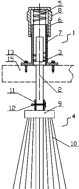
[0028] Such as figure 1 , figure 2 and image 3 As shown, the elastic broom comprises a cylinder body 1, a piston rod 2, a piston 3, a hair brush 4 and a stage clip 5, and the cylinder body 1 is arranged in an upside-down manner, that is, the opening of the cylinder body faces downward; The cylinder body is composed of an upper cylinder body 6 and a lower cylinder body 7 which are screwed together. Specifically, the upper cylinder body 6 is buckled on the upper part of the lower cylinder body 7, and the middle and lower inner wall of the upper cylinder body 6 is provided with an inner thread, the upper outer wall of the lower cylinder body 7 is provided with an external thread, and the internal thread and the external thread are screwed together. It should be specially noted that, relative to the position of the screw connection of the inner and outer threads, the lower port of the upper cylinder body 6 extends downward for a section, so as to protect the inner and outer th...

Embodiment 2

[0034] Such as Figure 4 , Figure 5 , Figure 6 , Figure 7 , Figure 8 and Figure 9As shown, the elastic broom comprises a cylinder body 1, a piston rod 2, a piston 3, a hair brush 4 and a stage clip 5, and the cylinder body 1 is arranged in an upside-down manner, that is, the opening of the cylinder body faces downward; The cylinder body is composed of an upper cylinder body 6 and a lower cylinder body 7 which are screwed together. Specifically, the upper cylinder body 6 is buckled on the upper part of the lower cylinder body 7, and the middle and lower inner wall of the upper cylinder body 6 is provided with an inner thread, the upper outer wall of the lower cylinder body 7 is provided with an external thread, and the internal thread and the external thread are screwed together. It should be specially noted that, relative to the position of the screw connection of the inner and outer threads, the lower port of the upper cylinder body 6 extends downward for a section,...


PUM


Abstract

The invention discloses a cleaning plate. The cleaning plate comprises a rotary plate and an elastic sweeper which is uniformly distributed on the rotary plate in a peripheral direction, wherein the elastic sweeper comprises a cylinder body, a piston rod, a piston, a hairbrush and a pressure spring, the piston is arranged on the piston rod; the piston rod can move back and forth along the inner wall of the cylinder body; the cylinder body is arranged in an inverted manner, namely, the opening of the cylinder faces downwards; the cylinder body comprises an upper cylinder body and a lower cylinder body which are in threaded connection with each other, wherein a ring-shaped bump is arranged on the outer side wall of the upper cylinder body; grains are arranged on the ring-shaped bump part, so that people can rotate the upper cylinder body conveniently; the pressure spring is mounted between the piston and the inner wall of the top of the upper cylinder body; the lower part of the piston rod penetrates through a cylinder lid; the lower end part of the piston rod is detachably connected with the hairbrush. The hairbrush of the cleaning plate can elastically stretch out and draw back according to fluctuation changes of a rod surface, so that abrasion of bristles is relieved, the service life of the hairbrush is prolonged; the upper and the lower cylinder bodies are in threaded connection so as to conveniently regulate the elastic force of the spring; moreover, the threaded connection part is free of interferences of outer dust.

Description

technical field [0001] The invention relates to a cleaning disc. Background technique [0002] Sweeper is a kind of environmental protection equipment for cleaning road garbage. It can reduce the labor intensity of sanitation workers to a certain extent, so it is praised as the main equipment for cleaning urban roads. The used cleaning disc of existing road sweeping vehicles mainly includes a rotating disc and some bundles of bristles fixed and evenly distributed on the rotating disc. When the sweeper is working, it is usually necessary to tilt the turntable so that the bristles on one side touch the ground, while the bristles on the other side are lifted off the ground. The bristles wear out quickly and need to be replaced frequently. Usually when replacing, the whole cleaning disc needs to be replaced together, and the rotating disc is often not damaged, and it can still work normally, but it is discarded together because the length of the bristles is not enough, which i...

Claims


Application Information

Patent Timeline
IPC IPC(8): E01H1/05
CPCE01H1/053
Inventor 张元晖
Owner 李丽容
Learn More