Pressure head assembly for assembling of engine valve lock plate

An engine valve and indenter technology, applied in the field of tooling and fixtures, can solve the problems of increasing the workload of workers, long production cycle, large free swing of valve springs, etc., and achieves the effect of convenient automatic assembly, solving industry problems and reliable action.

Inactive Publication Date: 2015-05-06
陈小利
View PDF6 Cites 4 Cited by
  • Summary
  • Abstract
  • Description
  • Claims
  • Application Information

AI Technical Summary

Problems solved by technology

The disadvantage of this press-fitting method is that the free swing of the valve spring on the cylinder head is relatively large, resulting in inaccurate positioning of the axis line of the valve stem, spring upper seat and pressure head during press-fitting, which may easily cause the lock plate to fail in press-fitting, resulting in Press-fitting cannot be completed smoothly, and the efficiency of press-fitting is low, which not only increases the workload of workers, but also requires higher proficiency of workers
The disadvantage is that the production cycle is longer (about 60 seconds); the pass rate is low (about 90%)
Moreover, the existing pressing equipment is basically manual equipment; foreign similar equipment is very complicated; the price is expensive; only a single pressing head part costs about 40,000 yuan

Method used


Image

  • Pressure head assembly for assembling of engine valve lock plate
  • Pressure head assembly for assembling of engine valve lock plate
  • Pressure head assembly for assembling of engine valve lock plate

Examples


Embodiment Construction

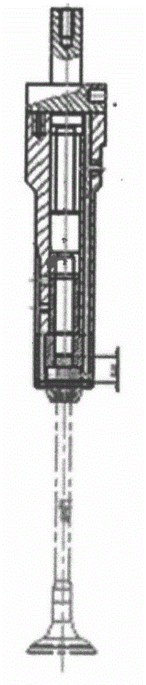
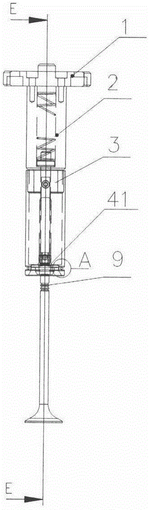
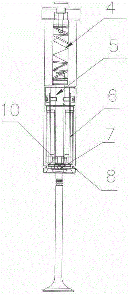
[0012] A pressure head assembly assembled with an engine valve lock plate, the pressure head assembly includes: a cover plate 1, a pressure head 2, a sleeve 3, a spring 4, a guide rod 5, a splint 6, a steel ball 7, a retaining spring 8, a cover The plate 1 is detachably connected to the pressure head 2. The spring 4 and the guide rod 5 are installed in the pressure head 2. One end of the spring 4 is pressed against the upper end of the guide rod 5; the other end is pressed against the cover plate 1, so that the guide rod 5 can move up and down;

[0013] A splint 6 is installed on the outside of the pressure head 2, which is used to clamp the locking plate 10 into the valve groove 9. The sleeve 3 and the pressure head 2 are connected by screws. The lower part of the sleeve 3 is engraved with an annular groove, and there are 2 tapered Hole, 1 steel ball 7 is respectively housed in the tapered hole, and annular groove also is equipped with jump ring 8, and jump ring 8 and steel ba...


PUM


Abstract

The invention discloses a pressure head assembly for assembling of engine valve lock plates. The pressure head assembly comprises a cover plate, a pressure head, a sleeve, a spring, a guide rod, a clamp plate, a steel ball and a snap ring, wherein the cover plate is detachably connected with the pressure head; the spring and the guide rod are arranged in the pressure head; one end of the spring presses the upper end of the guide rod and the other end of the spring abuts on the cover plate to ensure that the guide rod can move up and down; the clamp plate is mounted outside the pressure head and used for clamping a lock plate into a valve slot; the sleeve is connected with the pressure head by a screw; a circular groove is engraved in the lower part of the sleeve; two taper holes are formed in the circular groove; a steel ball is arranged in each taper hole; a snap spring is also arranged in the circular groove; the snap spring and the steel balls are used for fixing a spring upper seat on the pressure head. The pressure head assembly for assembling of engine valve lock plates is simple to manufacture and reliable in action; the production takt is less than or equal to 30 sec; the percent of pass is greater than or equal to 99%; refit can be directly carried out on the original equipment. According to the pressure head assembly for assembling of engine valve lock plates, the industrial difficulty of press fitting of trislot lock plates is effectively solved and the automatic assembling can be conveniently realized.

Description

technical field [0001] The invention relates to the technical field of fixtures, in particular to a pressure head assembly for assembly of three-slot lock plates for automobile engine valves. Background technique [0002] In the automobile industry, during the engine assembly process, the three-slot locking plate press-fitting is currently a difficult problem for the entire industry. At present, the valve lock plate assembly method adopted by various manufacturers is as follows: figure 1 : Install the locking piece in the upper seat of the spring, clamp it on the pressure head or place it on the valve spring, and press it through the press. The disadvantage of this press-fitting method is that the free swing of the valve spring on the cylinder head is relatively large, resulting in inaccurate positioning of the axis line of the valve stem, spring upper seat and pressure head during press-fitting, which may easily cause the lock plate to fail in press-fitting, resulting in ...

Claims


Application Information

Patent Timeline
Patent Type & Authority Applications(China)
IPC IPC(8): B23P19/02
CPCB25B27/02B25B27/0035
Inventor 陈小利
Owner 陈小利
Why Eureka
Try Eureka