A current-assisted thermoforming device and method using flexible clamping

A technology for flexible clamping and forming equipment, applied in the field of material processing, can solve problems such as spark ignition, and achieve the effects of improving temperature field distribution, saving energy consumption, and avoiding spark sparking

Active Publication Date: 2017-04-19
BEIJING SATELLITE MFG FACTORY
View PDF5 Cites 0 Cited by
  • Summary
  • Abstract
  • Description
  • Claims
  • Application Information

AI Technical Summary

Problems solved by technology

[0003] The technical problem to be solved by the present invention is: in order to overcome the deficiencies of the prior art, provide a current-assisted thermoforming equipment and method using flexible clamping, solve the problems of discharge and sparking in pulse current-assisted forming, and improve the metal matrix composite material. , titanium alloy, magnesium alloy, aluminum-lithium alloy and other hard-to-deform materials, improve the automation level of the forming process, reduce costs and save energy consumption

Method used


Image

  • A current-assisted thermoforming device and method using flexible clamping
  • A current-assisted thermoforming device and method using flexible clamping

Examples


Embodiment approach

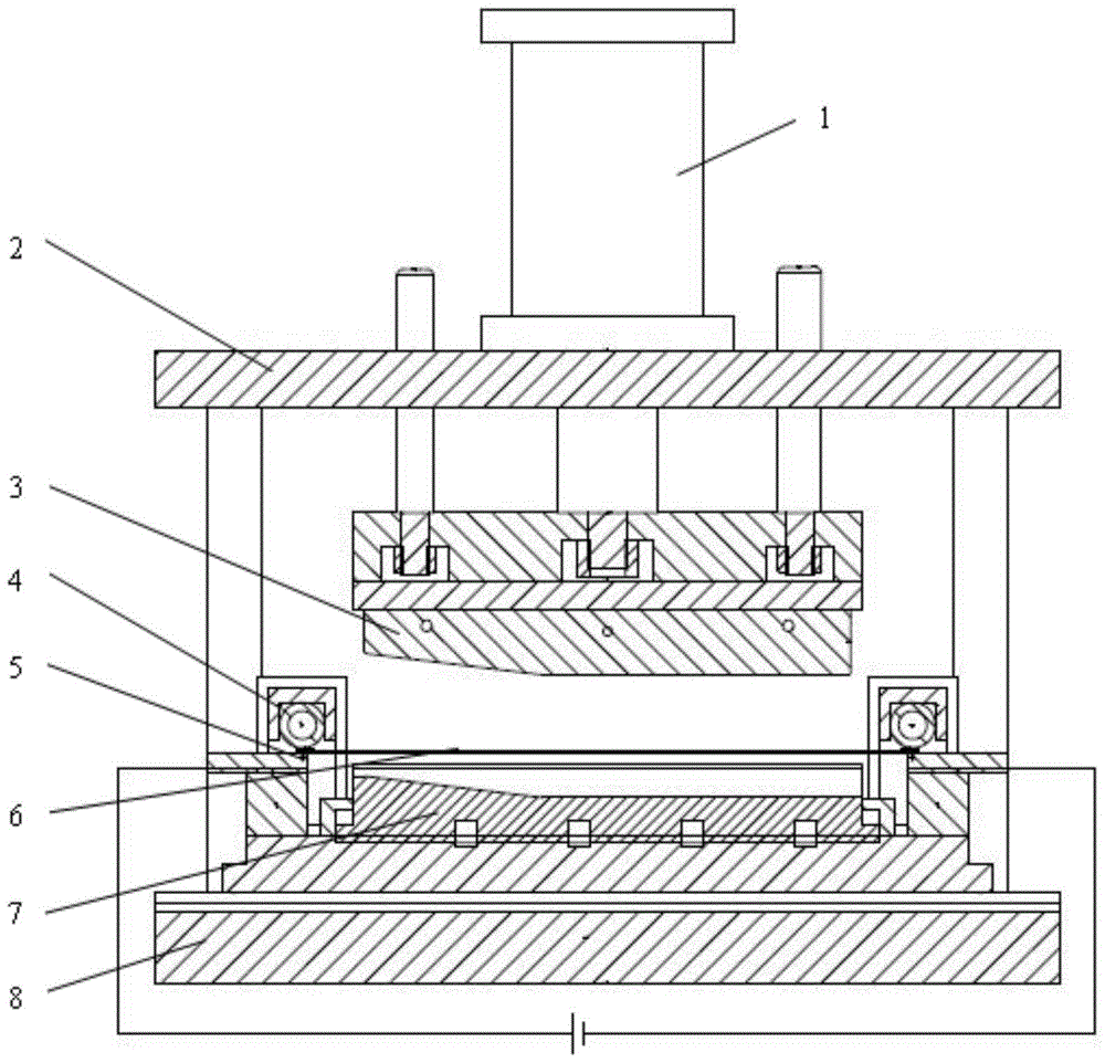
[0023] Combine below figure 1 Specifically explain the implementation of this equipment. The device used in this implementation mainly includes a hydraulic system, a forming mold, a flexible electrode clamping system, electrodes, a power supply and a control system, and a gas pressure control system. The working mode of pulse current assisted thermoforming equipment mainly includes the following steps:

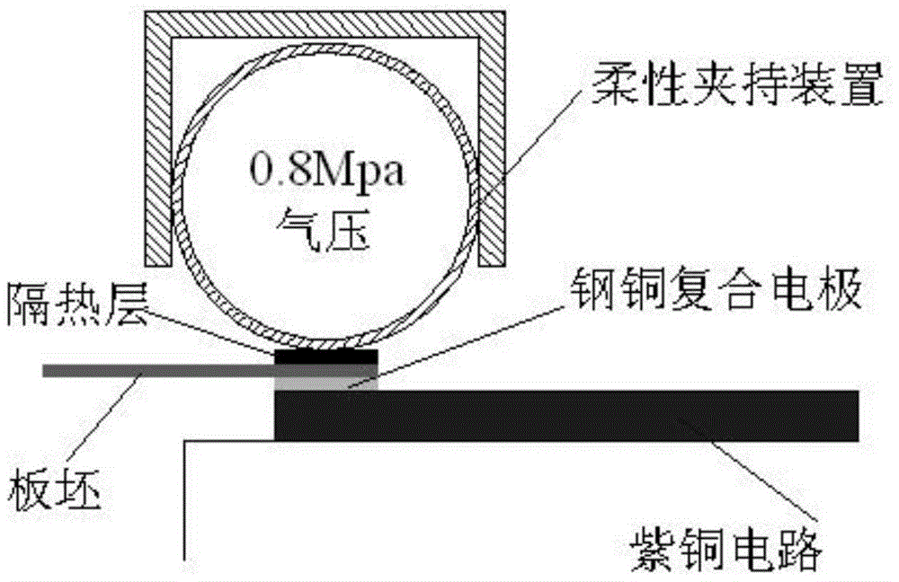
[0024] Step 1: Place the sheet in the pulse current assisted thermoforming equipment, inject compressed gas, and adjust the flexible holding force through the control system to ensure that the sheet and the electrode are well connected;

[0025] Step 2: Introduce high-intensity pulse current, the current flows through the circuit composed of electrodes and plates, and conducts electric heating;

[0026] Step 3: Use an infrared thermometer to measure and feed back the temperature of the energized plate in real time, adjust the pulse current in real time according to the temper...

specific Embodiment approach 2

[0033] Specific Embodiment 2: The difference between this embodiment and Embodiment 1 is that this embodiment adopts a pressing device to provide dynamic blank-holding force, and the others are the same as Embodiment 1.

specific Embodiment approach 3

[0034] Embodiment 3: The difference between this embodiment and Embodiment 1 is that this embodiment is aimed at the superplastic forming process, and the plate blank flange needs to use a ceramic mold, and the other is the same as Embodiment 1.


PUM


Abstract

The invention discloses a current auxiliary heat forming device with flexible clamping adopted. The device comprises a hydraulic system, a gas pressure control system, an upper platform, an upper die, flexible clamping systems, steel and copper composite electrode plates, a lower die and a lower platform. The upper die and the lower die are arranged between the upper platform and the lower platform. The hydraulic system installed on the upper platform controls the upper die to move towards the lower die. The steel and copper composite electrode plates are arranged at the two ends of the lower die, panel blanks are placed on the steel and copper composite electrode plates, and the flexible clamping systems are arranged at the two ends of the panel blanks. Each flexible clamping system comprises a semi-closed structure with one end open and a flexible pipe. The gas pressure control system provides gas pressure for the flexible pipes, the pipes are expanded out from the opening ends, and then the panel blanks are pressed. The forming of panels can be achieved when the dies are under the normal temperature state, the heat loss of the dies in the heating process and the energy needed for heating the dies to the set temperature do not exist, the forming efficiency of metal-based composite materials, titanium alloy, magnesium alloy, aluminum lithium alloy and other material panels hard to deform can be improved, the energy source consumption is reduced, and a very good energy saving effect is achieved.

Description

technical field [0001] The invention relates to a current-assisted thermoforming equipment and method using flexible clamping, which is suitable for precision thermoforming of difficult-to-deform materials such as metal-based composite materials, titanium alloys, magnesium alloys, and aluminum-lithium alloys, and belongs to the field of material processing. Background technique [0002] Metal matrix composites, titanium alloys, magnesium alloys, aluminum-lithium alloys, etc. have been widely used in high-tech fields, especially aerospace, due to their advantages of high strength and low density. The shape is poor, and it is a material that is difficult to deform at room temperature. The rigid electrode pressing device is prone to sparking and discharge, which affects the quality and efficiency of the forming; it is difficult to realize the forming of the material by using traditional processing technology, and it is usually necessary to heat this type of material to A certai...

Claims


Application Information

Patent Timeline
Patent Type & Authority Patents(China)
IPC IPC(8): B21D43/00B21D37/16
CPCB21D22/02B21D22/022B21D43/003
Inventor 王博赖小明张凯锋杜之豪
Owner BEIJING SATELLITE MFG FACTORY
Why Eureka
Try Eureka