Visual robot for abdominal cavity minimally-invasive surgery

A minimally invasive surgery and robotic technology, applied in the field of visual robotics, can solve the problems of the influence of the doctor's mood and fatigue, the high price of the robotic system, poor surgical accuracy and quality, etc., to achieve the effect of beautifying scars, increasing flexibility and freedom, less traumatic effect

Inactive Publication Date: 2015-05-06
HARBIN INST OF TECH
View PDF3 Cites 5 Cited by
  • Summary
  • Abstract
  • Description
  • Claims
  • Application Information

AI Technical Summary

Problems solved by technology

[0003] The present invention aims to solve the problem that existing hand-held or head-mounted visual surgical instruments are easily affected by the doctor's emotions and fatigue, have a low degree of intelligence, poor surgical accuracy and quality, and intelligent vision based on robot technology. Surgical robot systems are expensive, costly, and have poor flexibility and freedom, and then provide a visual robot for minimally invasive abdominal surgery

Method used


Image

  • Visual robot for abdominal cavity minimally-invasive surgery
  • Visual robot for abdominal cavity minimally-invasive surgery
  • Visual robot for abdominal cavity minimally-invasive surgery

Examples


specific Embodiment approach 1

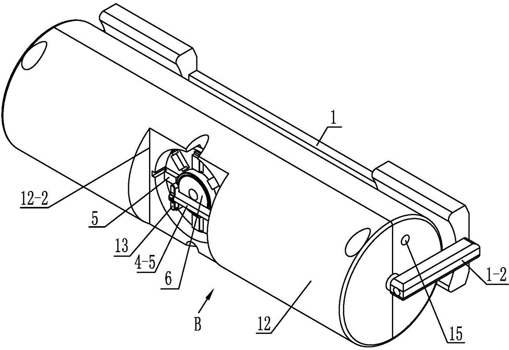
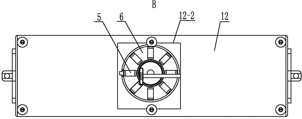
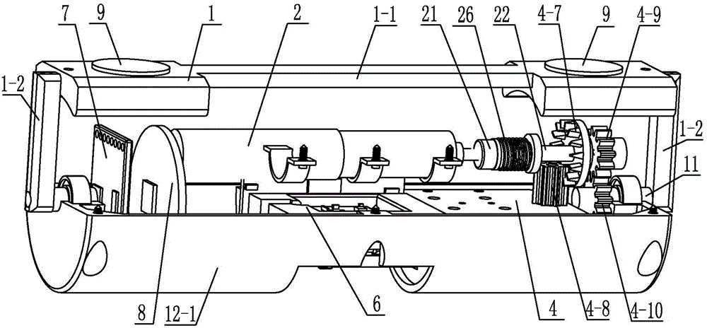
[0015] Specific implementation mode 1: Combination Figure 1-Figure 9 It is explained that the vision robot for minimally invasive abdominal surgery in this embodiment includes a housing 12 and a cleaning base 13; it also includes a three-segment shaft structure, a suspension bracket 1, a motor 2, a crank slider mechanism 4, a camera module 6, and wireless Transceiver module 7, central control circuit module 8, two permanent magnets 9, two fixed shafts 11 and multiple LED lights 5;

[0016] The three-segment shaft structure includes a first transmission shaft 21, a second transmission shaft 22, a third transmission shaft 20, a spring 26 and a square key 27. One end of the first transmission shaft 22 and one end of the second transmission shaft 21 are inserted into the two The square key 27 on the second transmission shaft 22 is connected with one end of the first transmission shaft 22 and one end of the second transmission shaft 21 is fitted with a spring 26 resting on the two. T...

specific Embodiment approach 2

[0024] Specific implementation manner two: combination Figure 8 Note that the sliding groove 4-11 of this embodiment is a dovetail groove or an inverted convex groove. This arrangement facilitates smooth sliding of the slider in the sliding groove, and can well wipe tissue fluid and water vapor on the lens by the cleaning substrate. Others are the same as the first embodiment.

specific Embodiment approach 3

[0025] Specific implementation mode three: combination image 3 , Figure 4 with Image 6 Note that the first cylindrical gear 4-9 and the second cylindrical gear 4-10 in this embodiment are both straight cylindrical gears. Easy to use and reliable, stable operation. Others are the same as the first or second embodiment.


PUM


Abstract

The invention provides a visual robot for abdominal cavity minimally-invasive surgery and relates to visual robots. The visual robot is used for solving the problems of the existing handheld or head-worn visual surgical instruments that during surgery, the surgery is easily affected by the mood and fatigue degree of a doctor, the intelligent degree is relatively low, the accuracy and quality of surgery are poor, and an intelligent visual surgical robot system based on a robot technology is expensive in price, high in cost and relatively poor in flexibility and freedom. The visual robot comprises a shell, a cleaning base body, a three-section shaft structure, a suspension bracket, a motor, a slider-crank mechanism, a camera module, a wireless transceiver module, a central control circuit module, two permanent magnets, two fixing shafts and a plurality of LED (Light Emitting Diode) lamps, wherein the three-section shaft structure comprises a first transmission shaft, a second transmission shaft, a third transmission shaft, a spring and a square key; the slider-crank mechanism comprises a driving shaft, a crank, a link lever, a slider, a connecting rod, a guide rail, a coronary gear, a spur gear, a first cylindrical gear and a second cylindrical gear. The visual robot is applied to the abdominal cavity minimally-invasive surgery.

Description

Technical field [0001] The invention relates to a visual robot, in particular to a visual robot for minimally invasive abdominal surgery. It replaces the role of an endoscope in minimally invasive abdominal surgery, provides illumination for the operating area, and displays the operating area through a camera module The field of view is photographed and transmitted to a monitor outside the body to assist the doctor in the operation. Background technique [0002] Minimally invasive surgery has the advantages of small incision, light pain, less tissue damage, short postoperative recovery period, beautification of scars and low postoperative recurrence rate. It is helpful to improve people's quality of life and the pursuit of beauty. It is widely used in surgery. At present, most mature minimally invasive surgeries are performed by inserting surgical instruments into the human body through 3 to 5 tiny incisions. Reducing the number of incisions can help improve the quality of the o...

Claims


Application Information

Patent Timeline
Patent Type & Authority Applications(China)
IPC IPC(8): A61B19/00
Inventor 封海波付宜利马腾飞吕毅董鼎辉
Owner HARBIN INST OF TECH
Why Eureka
Try Eureka