Eureka AIR delivers breakthrough ideas for toughest innovation challenges, trusted by R&D personnel around the world.

Directional modulation signal design method based on reverse antenna array.

A reverse antenna array and directional modulation technology, applied in diversity/multi-antenna systems, phase-modulated carrier systems, space transmit diversity, etc., can solve problems such as inability to achieve full space coverage

Active Publication Date: 2015-04-29
NANJING UNIV OF POSTS & TELECOMM
View PDF4 Cites 32 Cited by
  • Summary
  • Abstract
  • Description
  • Claims
  • Application Information

AI Technical Summary

Problems solved by technology

Hong-zhe Shi published "Enhancing the security of communication via directly modulated antenna arrays" in IET Microwaves, Antennas&Propagation, VOL.7, NO.8, 2013. In the paper, a 2-bit digital phase shifter is proposed for comprehensive direction modulation signal, but the direction modulation signal synthesis method based on the digital phase shifter can only synthesize the direction modulation signal in the discrete and limited direction in space, and cannot achieve full space coverage. If the legal user is not in the discrete space set, it needs to be adjusted The array spacing of the transmitting array, this method also has certain problems in practical engineering applications

Method used


Image

  • Directional modulation signal design method based on reverse antenna array.
  • Directional modulation signal design method based on reverse antenna array.
  • Directional modulation signal design method based on reverse antenna array.

Examples


Embodiment 1

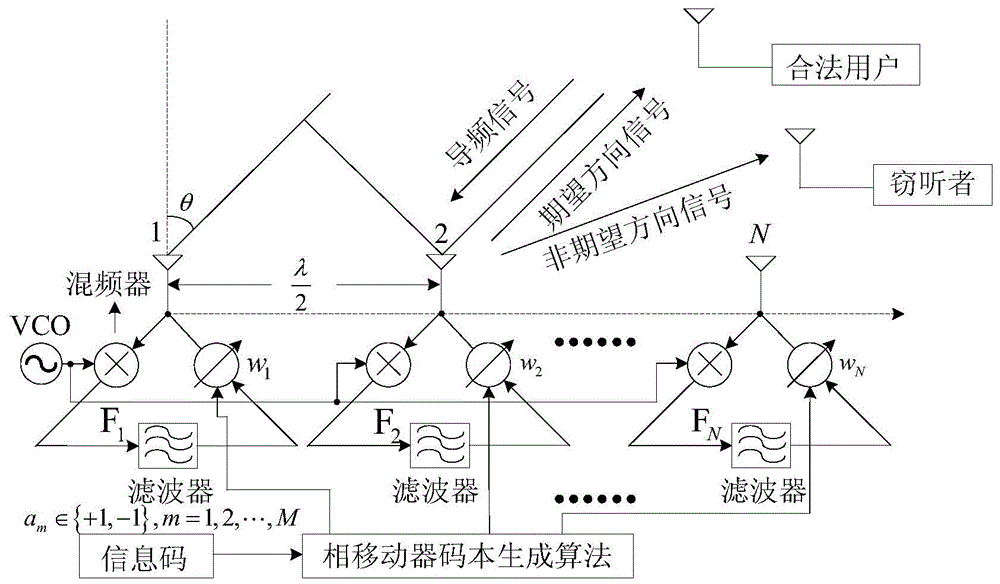
[0038] The invention will be described in further detail below in conjunction with the accompanying drawings.

[0039] Phase shifter codebook generation method of the present invention comprises as follows:

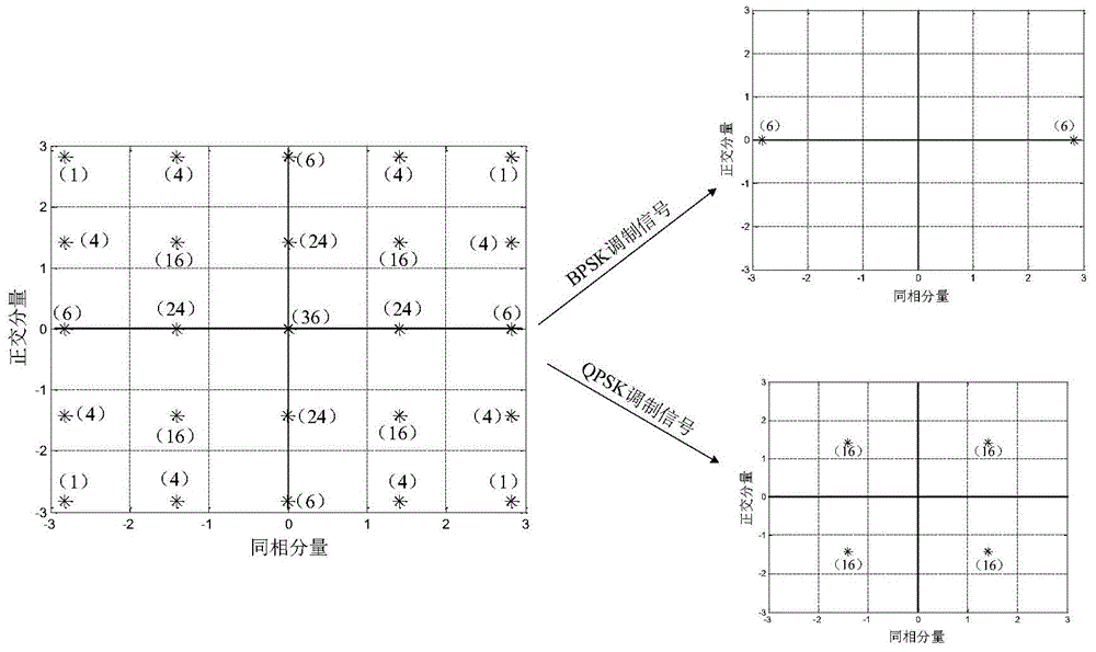
[0040]Assuming that the number of transmitting antennas in the transmitting system is N=4, the phase shifter uses a 2-bit digital phase shifter, and the corresponding weighting coefficient The phase shifter phase shifts a total of (2 l ) N =256 phase combinations, corresponding to 256 constellation points, The constellation diagram of 256 points is as follows figure 2 As shown, the numbers next to the constellation points in the figure indicate the number of different phase combinations that can generate the same constellation point, and 256 phase sets correspond to the production of 25 symmetrical constellation points. Different constellation points can be selected from 25 constellation points to form BPSK signals, QPSK signals and other expected integrated baseba...

Embodiment 2

[0042] The dynamic direction modulation signal of the present invention comprises as follows:

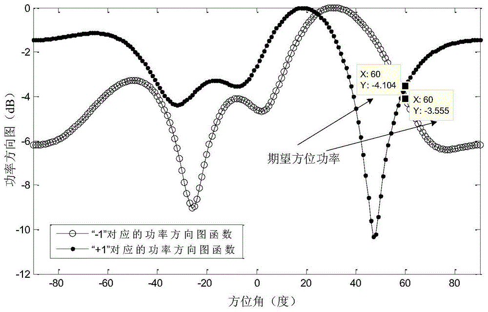
[0043] Assuming that the number of transmitting antennas in the transmitting system is N=4, the phase shifter is a 2-bit digital phase shifter, the expected integrated baseband digital modulation signal is a QPSK signal, and the expected position of the receiver is θ 1 =40°, the azimuth θ where the eavesdropping receiver is located 2 = 60°. Depend on Figure 9 It can be seen that the same QPSK constellation point corresponds to 16 different phase combinations. When sending the same QPSK modulation symbol, different phase combinations can be randomly selected from the codebook, so that the constellation diagram of the received signal of the eavesdropping receiver in the undesired direction presents a process of dynamic change. . Fig. 4 and Fig. 5 respectively show the comparison of the received signal constellation diagrams of the desired azimuth and the undesired azimuth of stati...

Embodiment 3

[0045] Arbitrary directions in space of the present invention synthesize desired direction modulation signals and include as follows:

[0046] For the traditional direction modulation signal based on phased array, if a 2-bit digital phase shifter is used, the position of the desired receiver that can synthesize the symmetrical constellation diagram must satisfy the following formula:

[0047] 2 π λ d sin θ = π 2 K , K = . . . , - 2 , - 1 , 0,1,2 , . . . - - - ( 5 )

[0048] Then it can be obtained from formula (5) that the azimuth θ must satisfy:

[0049] θ ...


PUM


Abstract

The invention discloses a directional modulation signal design method based on a reverse antenna array. According to the method, the reverse antenna array is adopted to enable an incident wave phase position to conjugate and enable a digital phase shifter to construct a directional modulation signal planisphere codebook, and an expected directional modulation signal is synthesized in any spatial direction; according to the invention, a directional modulation signal transmitter and two common digital signal receivers in different spatial directions are included; the spatial direction where the legal user receiver is positioned is the expected direction, and the spatial direction where the eavesdropping receiver is positioned is the unexpected direction. A legal user can normally demodulate a received signal by utilizing the directional modulation signal transmitted through the method; however, the eavesdropping receiver cannot demodulate useful communication information even if receives signal energy similar to that of the legal user due to the dynamic distortion of a received signal planisphere. Therefore, the transmitted directional modulation signal provides a secure transmission method for wireless transmission of communication information.

Description

technical field [0001] The invention relates to a design method of a direction modulation signal based on a reverse antenna array, and belongs to the technical field of wireless communication. Background technique [0002] Today, with the wide application of wireless communication technology in different industries, the security of communication information in the process of transmission has attracted more and more attention. For wireless communication transmitters with traditional modulation methods, the modulation function of the digital communication signal is completed in the baseband, and then the transmitting antenna is excited by the amplifier to radiate wireless communication information. The wireless communication signal transmitted in this way is within the range of the main lobe and the direction of the side lobe. The signal received by the eavesdropping receiver has the same modulation signal constellation as the signal received by the legitimate user in the dire...

Claims


Application Information

Patent Timeline
Patent Type & Authority Applications(China)
IPC IPC(8): H04B7/04H04L27/20
Inventor 洪涛宛汀梁雪松
Owner NANJING UNIV OF POSTS & TELECOMM
Why Eureka
Eureka Blog
Learn More