Single-board multi-way high-voltage power silicon-controlled trigger circuit

A trigger circuit, thyristor technology, applied in electrical components, electronic switches, pulse technology, etc., to achieve the effect of small circuit board size, strong environmental adaptability, and good electromagnetic compatibility performance

Inactive Publication Date: 2015-04-29
SOUTH WEST INST OF TECHN PHYSICS
View PDF6 Cites 2 Cited by
  • Summary
  • Abstract
  • Description
  • Claims
  • Application Information

AI Technical Summary

Problems solved by technology

[0004] The object of the present invention is to aim at the deficiencies in the above-mentioned prior art, on the basis of the general thyristor trigger circuit, to provide a high-reliability single-board multi-channel high-voltage power thyristor trigger circuit, which has a trigger Large current, good synchronization of parallel triggering, high isolation, strong anti-interference performance and single-board integration, etc., to solve the special triggering requirements of pulse power switches and complex electromagnetic environments in high-energy laser power supplies

Method used


Image

  • Single-board multi-way high-voltage power silicon-controlled trigger circuit
  • Single-board multi-way high-voltage power silicon-controlled trigger circuit

Examples


Embodiment Construction

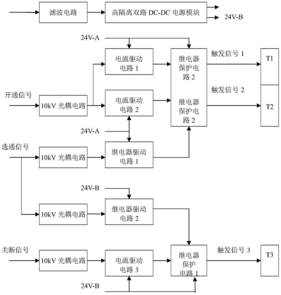
[0017] exist figure 1 Among them, the single-board multi-channel high-voltage power thyristor trigger circuit is mainly composed of 4 sets of 10kV optocoupler circuits, 3 sets of current drive circuits (including energy storage capacitors), 2-way relay drive circuits, 3-way relay protection circuits and high isolation dual It consists of a DC / DC power supply module and its input filter circuit. The current driving circuit is provided with a trigger current by the TIP107 power transistor. Two sets of 10kV optocoupler circuits are electrically connected to three sets of current drive circuits to form a three-way trigger pulse synchronous trigger circuit. The trigger signal 1 and trigger signal 2 in the three-way trigger circuit are driven by the same turn-on signal through the same set of optocoupler circuits. Two current drive circuits with the same circuit form and circuit parameters are generated, and the other trigger circuit turns off the signal 10kV optocoupler circuit se...


PUM


Abstract

The invention provides a single-board multi-way high-voltage power silicon-controlled trigger circuit and aims to provide a trigger circuit which is large in trigger current, good in trigger synchronicity, high in isolation degree and high in anti-disturbance performance. The trigger circuit is obtained through the following technical scheme. According to the technical scheme, two sets of optical coupler circuits are correspondingly and electrically connected with three sets of current drive circuits to form three trigger circuit bodies with synchronous trigger pulses, two trigger signals in the three trigger circuit bodies are generated through the same on-signal in the mode that the same set of optical coupler circuits drives the two current drive circuits with completely identical circuit forms and circuit parameters, and the turn-off signal optical coupler circuit of another trigger circuit body is sequentially connected with the current drive circuits in series to generate a trigger signal 3; the other two sets of optical coupler circuits are connected with relay drive circuits 1 and 2 respectively in series, gating signal control and trigger signal output end relay short circuit protection are adopted for improving the anti-interference property of the trigger circuit; high isolation optical couplers are adopted in the four sets of optical coupler circuits to increase the isolation degree between input signals and the trigger signals, and a double-way DC / DC power source module supplies power.

Description

technical field [0001] The invention relates to a high-voltage power thyristor trigger circuit mainly used for high-energy laser power pulse power switch. More specifically, the invention is a high-reliability single-board multi-channel high-voltage power thyristor trigger circuit that can be used in complex electromagnetic environments. technical background [0002] The pumping of high-energy solid-state lasers generally requires a pulse power switch to control or switch. The main switching elements that make up the pulse power switch are multiple high-voltage power thyristors, some of which need to be triggered synchronously and used in parallel to increase the passing current; some thyristors are used independently and need to be isolated from each other. Generally, the pulse power switch in the high-energy laser power supply withstands a voltage greater than 5kV and a passing current of 20kA. The electromagnetic environment in which the trigger circuit is located is ver...

Claims


Application Information

Patent Timeline
IPC IPC(8): H03K17/72H03K17/78
Inventor 林菊平李慧君贺廿六赵才曲唐伟白杨黄炼童勇赖厚川王国帅刘攀
Owner SOUTH WEST INST OF TECHN PHYSICS
Why Eureka
Try Eureka