
Optimal current waveform controlling method for current type two-way DC-DC convertor

A DC-DC and current waveform technology, applied in the direction of converting DC power input to DC power output, adjusting electrical variables, and controlling/regulating systems, can solve the problem of not being able to fully utilize the power transfer of the transformer and fully reduce the current of the switch tube on the low-voltage side Stress and other issues, to achieve the effect of reducing the circulating current device

Active Publication Date: 2015-04-29
BEIJING INSTITUTE OF TECHNOLOGYGY
View PDF3 Cites 30 Cited by
  • Summary
  • Abstract
  • Description
  • Claims
  • Application Information

AI Technical Summary

Problems solved by technology

However, under the same working conditions, this method cannot make full use of the stage when the low-voltage side voltage of the transformer is not zero for power transfer, and cannot fully reduce the current stress of the low-voltage side switching tube.

Method used


Image

  • Optimal current waveform controlling method for current type two-way DC-DC convertor
  • Optimal current waveform controlling method for current type two-way DC-DC convertor
  • Optimal current waveform controlling method for current type two-way DC-DC convertor

Examples


Embodiment Construction

[0042] The present invention will be described in detail below in conjunction with accompanying drawing and embodiment, also described the technical problem and beneficial effect that the technical solution of the present invention solves simultaneously, it should be pointed out that described embodiment is only intended to facilitate the understanding of the present invention, and It has no limiting effect on it.

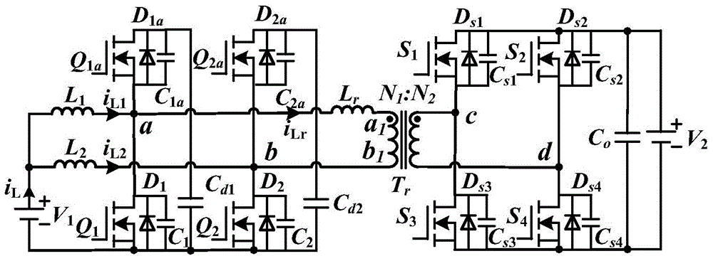
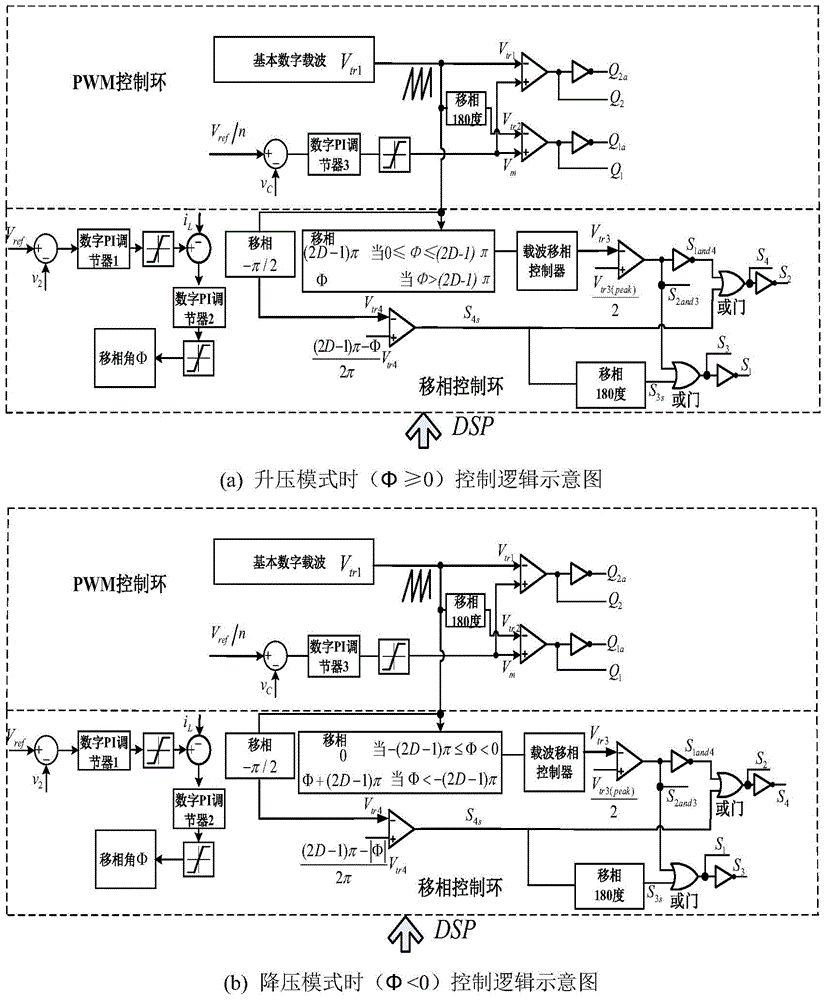
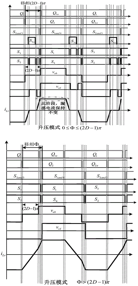
[0043] In this embodiment, an optimal current waveform control method for a current-mode bidirectional DC-DC converter is based on figure 1 The circuit shown realizes that i L is the low-voltage side current, i L1 i L2 are the input inductance L 1 , L 2 current, i Lr is the leakage inductance current, and the output voltage of the high voltage side of the converter is V 2 , the voltage on the primary side of the transformer is the voltage v between two points a and b ab , the secondary voltage of the transformer is the voltage v between the two points c and ...


PUM


Abstract

The invention relates to an optimal current waveform controlling method for a current type two-way DC-DC convertor, and belongs to the power electronics field of the high frequency switch power source direction. According to the method, by simultaneously adjusting the duty ratio of a low voltage side and the conductive logic of two bridge arm switching tubes of a high voltage side, so that when the voltage of the low voltage side of a transformer reaches zero, a leakage inductance current of the transformer maintains the cocurrent change, the dynamic change of the leakage inductance current is completed so that the maximum peak value can be reached, when the voltage of the low voltage side of a transformer does not reach zero, the peak value of the leakage inductance current is guaranteed to be minimum under the condition of transmitting the same power. Therefore, the current-circulation loss and the conduction loss of circuits and the switching tubes and the current stress of power devices are greatly reduced, and the efficiency and performance of the circuits are improved. Meanwhile, although conducting logics of secondary side switching tubes during a boost mode and a buck mode are slightly different, the seamless switching can be achieved between the boost mode and the buck mode, so that a closed loop real-time control on the system can be easily achieved.

Description

technical field [0001] The invention relates to an optimal current waveform control method, in particular to an optimal current waveform control method applied to an isolated current type bidirectional DC-DC converter, belonging to the direction of high-frequency switching power supply in the field of power electronics. Background technique [0002] For a current-mode bidirectional DC-DC converter used in high-voltage applications, the low-voltage side adopts a current-mode half-bridge topology with an active clamp circuit, and the high-voltage side adopts a full-bridge topology. The current-mode half-bridge topology with an active clamp circuit on the low-voltage side can reduce the current ripple on the low-voltage side and improve the service life of the battery. The high-voltage side adopts a full-bridge topology, which can minimize the circulation loss by controlling its switching logic. For bidirectional DC-DC converters, the high current stress of the low-side switch...

Claims


Application Information

Patent Timeline
IPC IPC(8): H02M3/335
CPCH02M3/33592
Inventor 沙德尚许国刘弘耀李斌
Owner BEIJING INSTITUTE OF TECHNOLOGYGY
Learn More