


Quick Research
Generate reliable direction feasibility study reports for your R&D in just a few steps.

Technical Q&A
Discover and master advanced knowledge NOW. Basics, ideas, possibilities, all at once.

Find Solutions
As an expert in R&D theories, this can generate solutions to your technical problems instantly.

Evaluate Feasibility
Analyze your overall solution with one click, know your potential R&D risks in advance.

Monitor Landscape
Get weekly tech updates, stay abreast of the latest tech innovations and key insights.
Ventilation channel steel, its manufacturing method, ventilation structure and motor
A ventilation channel steel and superior technology, which is applied in the field of ventilation structure, motor and ventilation channel steel, can solve the problems affecting the heat dissipation coefficient of the motor surface and local pressure drop, the difficulty of ventilation channel steel, and the influence on the temperature rise of the motor, etc., to achieve enhanced cooling and heat dissipation The effect of low manufacturing difficulty and low processing cost
- Summary
- Abstract
- Description
- Claims
- Application Information
AI Technical Summary
Problems solved by technology
Method used
Image

Examples
Embodiment 1
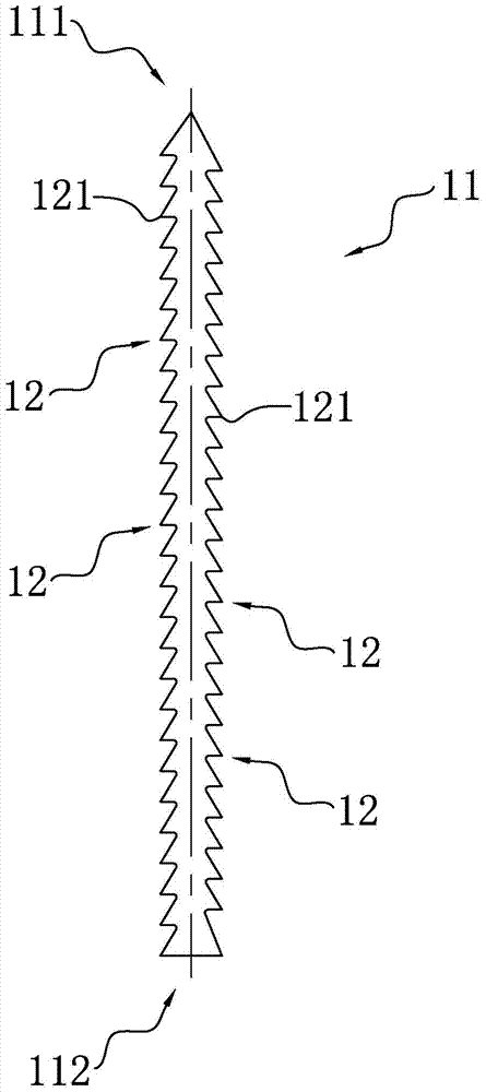
[0050] like figure 1 As shown, it is a schematic structural diagram of the ventilation channel steel in Embodiment 1 of the present invention. The ventilation channel steel according to Embodiment 1 of the present invention comprises a ventilation channel steel body 11, on at least one of the two opposite sides of the ventilation channel steel body 11 (for example, two as shown in the figure) tooth 12.
[0051] The ventilation channel steel in Embodiment 1 of the present invention is different from the commonly used traditional "I"-shaped ventilation channel steel and strip-shaped ventilation channel steel. The teeth 12 provided on the side of the ventilation channel steel body 11 can at least bring the following advantages:
[0052] 1. It can effectively break the boundary layer between the ventilation channel steel and the cooling gas flowing through the ventilation ditch, significantly increase the turbulent flow of the cooling gas, and make the cooling gas fully contact wit...
Embodiment 2
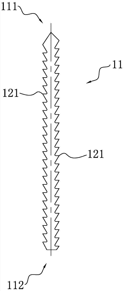
[0062] like figure 2 As shown, it is a schematic structural diagram of the ventilation channel steel of the second embodiment of the present invention. The teeth of the ventilation channel steel of this embodiment are also triangular teeth 121, and its tooth profile is also a line segment with two common endpoints. The difference between the ventilation channel steel of this embodiment and the ventilation channel steel of Embodiment 1 is that these two The length of the line segment near the upwind end 111 of the ventilation channel steel body 11 in the line segment is less than the length of the line segment near the downwind end 112 of the ventilation channel steel body 11, that is, the tip of the triangular tooth 121 is more towards the upstream side of the cooling gas, This can effectively increase the collision area between the triangular teeth 121 and the cooling air, generate greater turbulent flow effect, and widen the width of airflow in a high turbulent state on the...
Embodiment 3
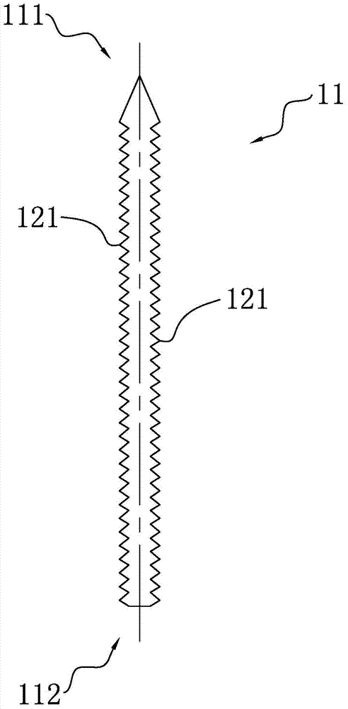
[0064] like image 3 As shown, it is a structural schematic diagram of the ventilation channel steel of the third embodiment of the present invention. The teeth of the ventilation channel steel of this embodiment are also triangular teeth 121, and the tooth profiles are also two line segments with common endpoints. The main difference between the ventilation channel steel of this embodiment and the ventilation channel steel of the previous embodiment is: the two The length of the line segment near the upwind end 111 of the ventilation channel steel body 11 in the line segment is equal to the length of the line segment near the downwind end 112 of the ventilation channel steel body 11, that is, the tip of the triangular tooth 121 faces perpendicular to the ventilation channel steel body 11 This shape is a compromise between the tooth shapes in Embodiment 1 and Embodiment 2. Compared with Embodiment 1, it can produce a greater turbulence effect, and compared with Embodiment 2, i...
PUM
 Abstract
Description
Claims
Application Information
 - R&D Engineer
- R&D Manager
- IP Professional
- Industry Leading Data Capabilities
- Powerful AI technology
- Patent DNA Extraction
Browse by: Latest US Patents, China's latest patents, Technical Efficacy Thesaurus, Application Domain, Technology Topic, Popular Technical Reports.
© 2024 PatSnap. All rights reserved.Legal|Privacy policy|Modern Slavery Act Transparency Statement|Sitemap|About US| Contact US: help@patsnap.com