Controller fault detection system of intelligent transmitter

An intelligent transmitter and fault detection technology, which is applied in the general control system, control/regulation system, test/monitoring control system, etc., can solve the problems of inaccurate transmitter control, difficult wiring, and technical difficulty. To achieve the effect of accurate and clear logic control, avoiding line connection and reducing the cost of use

Active Publication Date: 2015-04-29
重庆四联测控技术有限公司 +1
View PDF6 Cites 4 Cited by
  • Summary
  • Abstract
  • Description
  • Claims
  • Application Information

AI Technical Summary

Problems solved by technology

[0002] Smart transmitters have been widely used in industrial control. When the controller of the smart transmitter (referred to as CPU in English) fails and the current output fails, the main solution is to use transmitter redundancy to judge and detect the fault. That is: add another intelligent transmitter at the same position as the original transmitter, and use two transmitters to collect and output data at the same time. If one of them fails, then the output value of the other transmitter will be used. Compared with the output value of the faulty transmitter, then judge and detect the fault, and carry out alarm processing through the detection device or system, the cost of using the above method is extremely high, and the wiring on site is difficult. It is technically difficult for the transmitter to perform programming, judgment and other operations; therefore, a dual-CPU method has gradually been proposed, that is to say, two controllers are set in the intelligent transmitter, and within the allowable range of power consumption, Using one of the CPUs to monitor the other CPU, this method is likely to cause logic confusion, resulting in inaccurate control of the transmitter, the same industrial programming and development difficulties, and on-site wiring difficulties

Method used


Image

  • Controller fault detection system of intelligent transmitter
  • Controller fault detection system of intelligent transmitter
  • Controller fault detection system of intelligent transmitter

Examples


Embodiment Construction

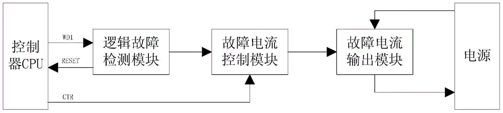
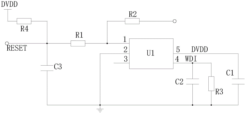
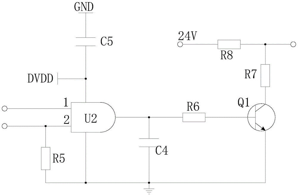
[0015] figure 1 It is a block diagram of the present invention, figure 2 It is the circuit diagram of the logical fault detection module of the present invention, image 3 It is the circuit diagram of the fault current control module of the present invention, Figure 4 It is a circuit diagram of the fault current output module of the present invention, as shown in the figure, the controller fault detection system of the intelligent transmitter provided by the present invention includes a logical fault detection module connected with the controller of the intelligent transmitter, and the A fault current control module connected to the logic fault detection module, a fault current output module connected to the fault current control module, and a power supply, the fault current control module is also connected to the controller, and the power supply terminal of the fault current output module is connected to the power supply; The controller failure detection system of the int...


PUM


Abstract

The invention provides a controller fault detection system of an intelligent transmitter. The controller fault detection system comprises a logic fault detection module, a fault current control module, a fault current output module and a power source. The logic fault detection module is connected with a controller of the intelligent transmitter, the fault current control module is connected with the logic fault detection module, and the fault current output module is connected with the fault current control module. The fault current control module is further connected with the controller, and the power source end of the fault current output module is connected with the power source. The fault of the controller of the intelligent transmitter can be accurately detected, complex circuit connection can be avoided, and it can be ensured that the logic control of the controller is accurate and clear; the structure is simple, and the using cost is effectively lowered.

Description

technical field [0001] The invention relates to the field of intelligent transmitters, in particular to a controller fault detection system of an intelligent transmitter. Background technique [0002] Smart transmitters have been widely used in industrial control. When the controller of the smart transmitter (referred to as CPU in English) fails and the current output fails, the main solution is to use transmitter redundancy to judge and detect the fault. That is: add another intelligent transmitter at the same position as the original transmitter, and use two transmitters to collect and output data at the same time. If one of them fails, then the output value of the other transmitter will be used. Compared with the output value of the faulty transmitter, then judge and detect the fault, and carry out alarm processing through the detection device or system, the cost of using the above method is extremely high, and the wiring on site is difficult. It is technically difficult...

Claims


Application Information

Patent Timeline
Patent Type & Authority Applications(China)
IPC IPC(8): G05B23/02
CPCG05B23/0218
Inventor 艾军赵俊奎张宇
Owner 重庆四联测控技术有限公司
Why Eureka
Try Eureka