Liquid crystal display panel and liquid crystal display device

A technology of liquid crystal display panel and liquid crystal display device, which is applied in static indicators, nonlinear optics, instruments, etc., can solve the problems of poor display of liquid crystal display device and large difference in output pulse of scanning signal, etc., and achieve the effect of improving display effect

Active Publication Date: 2015-04-29
TCL CHINA STAR OPTOELECTRONICS TECH CO LTD
View PDF5 Cites 2 Cited by
  • Summary
  • Abstract
  • Description
  • Claims
  • Application Information

AI Technical Summary

Problems solved by technology

[0005] The object of the present invention is to provide a kind of liquid crystal display panel and the liquid crystal display device that the scan signal output pulse difference of a kind of different driving chips is less; The difference is large, leading to the technical problem of poor display of the liquid crystal display device

Method used


Image

  • Liquid crystal display panel and liquid crystal display device
  • Liquid crystal display panel and liquid crystal display device
  • Liquid crystal display panel and liquid crystal display device

Examples


Embodiment Construction

[0033] The following descriptions of the various embodiments refer to the accompanying drawings to illustrate specific embodiments in which the present invention can be practiced. The directional terms mentioned in the present invention, such as "up", "down", "front", "back", "left", "right", "inside", "outside", "side", etc., are for reference only The orientation of the attached schema. Therefore, the directional terms used are used to illustrate and understand the present invention, but not to limit the present invention.

[0034] In the figures, structurally similar units are denoted by the same reference numerals.

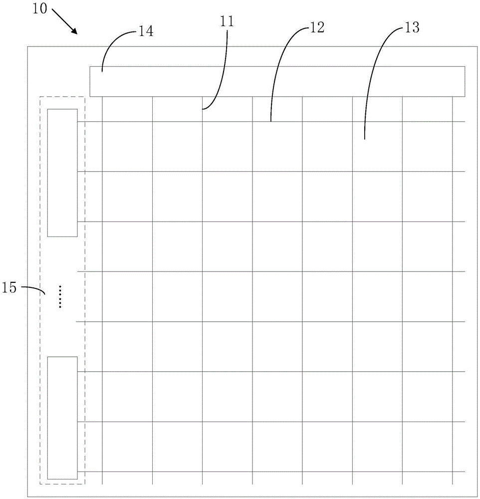
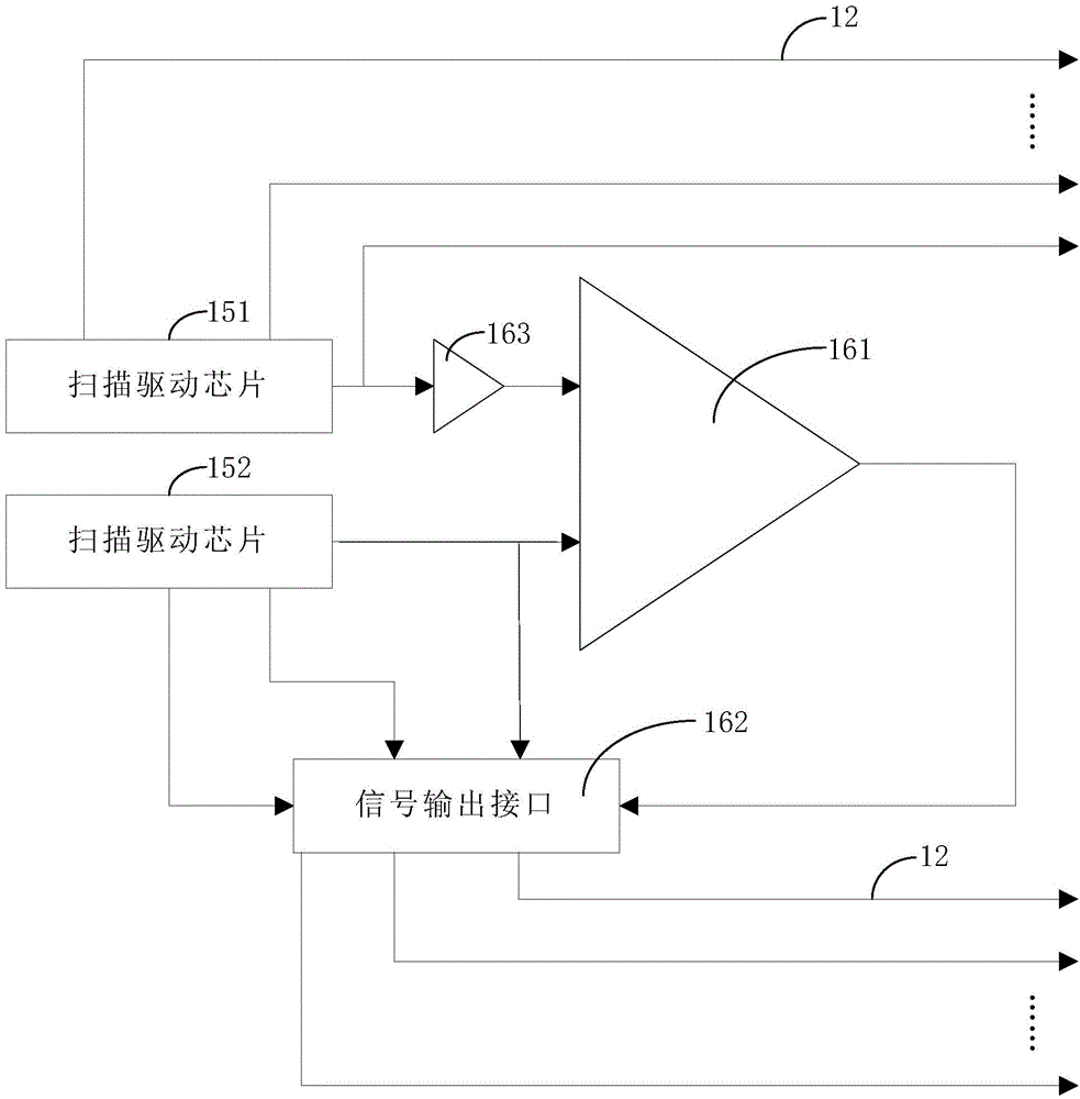
[0035] Please refer to figure 1 and figure 2 , figure 1 It is a schematic structural diagram of a preferred embodiment of the liquid crystal display panel of the present invention; figure 2 It is a structural schematic diagram of the scan driving chipset and the comparison unit of the preferred embodiment of the liquid crystal display panel of the prese...


PUM


Abstract

The invention provides a liquid crystal display panel. The liquid crystal display panel comprises a data line, a scanning line, a pixel unit, a data drive chip, a scanning drive chip group and a comparison unit, wherein the comparison unit is respectively connected with two scanning drive chips and used for performing signal compensation on the scanning signal output by one of the scanning drive chip according to the scanning signal output by the other scanning drive chip so as to allow the difference of the scanning signals output by the two scanning drive chips to be lower than a set value. The invention further provides a liquid crystal display device. The liquid crystal display panel and the liquid crystal display device have the advantages that by the comparison unit, the output pulse difference of the scanning signals of the different drive chips is allowed to be small, and the display effect of the liquid crystal display device is increased.

Description

technical field [0001] The invention relates to the field of liquid crystal display, in particular to a liquid crystal display panel and a liquid crystal display device. Background technique [0002] As a high-quality flat-panel display device, a liquid crystal display device has the advantages of small size, low power consumption, high resolution, high color saturation, and fast image refresh rate. The liquid crystal display panel generally uses an external driver chip to charge the pixel capacitance in the liquid crystal display panel in a progressive scanning manner. [0003] Usually, the plug-in driver chip has two packaging methods: COF (Chip On Film, chip set on a film) and COG (chip on glass, chip set on a glass plate). , the scan signal output pulses of different driving chips will be different; thus, the pixel switching capabilities of different pixels will be different, resulting in the display defect of the corresponding liquid crystal display device H-block. ...

Claims


Application Information

Patent Timeline
Patent Type & Authority Applications(China)
IPC IPC(8): G02F1/133G09G3/36
CPCG09G3/3648G09G2230/00G02F1/133G09G3/36G09G3/3677
Inventor 徐向阳
Owner TCL CHINA STAR OPTOELECTRONICS TECH CO LTD
Why Eureka
Try Eureka