
Installing structure of electric capacity type liquidometer

An installation structure and liquid level gauge technology, applied in the field of liquid level gauges, can solve the problems of abnormal signal transmission, easy falling off of the connection structure, and improper connection, so as to reduce self-interfering signals, avoid spot welding connections, and be firm and not easy to fall. broken effect

Inactive Publication Date: 2015-04-29
SHANGHAI RENYWELL TECH
View PDF7 Cites 3 Cited by
  • Summary
  • Abstract
  • Description
  • Claims
  • Application Information

AI Technical Summary

Problems solved by technology

The installation steps are cumbersome, which may cause improper connection, abnormal signal transmission or interference, and the installation structure is not strong enough and easy to loose. Since the connecting piece needs to pass through the liquid, it is necessary to connect the connecting piece and the base ring. Welding, the connection structure is easy to fall off. For a large gas cylinder that uses a liquid level gauge to measure the liquid level, the scrapping of the liquid level gauge is equal to the scrapping of the gas cylinder itself, causing serious losses

Method used


Image

  • Installing structure of electric capacity type liquidometer
  • Installing structure of electric capacity type liquidometer
  • Installing structure of electric capacity type liquidometer

Examples


Embodiment Construction

[0021] In order to make the above objects, features and advantages of the present invention more comprehensible, specific implementations of the present invention will be described in detail below in conjunction with the accompanying drawings.

[0022] In the following description, numerous specific details are set forth in order to provide a thorough understanding of the present invention. However, the present invention can be implemented in many other ways different from those described here, and those skilled in the art can make similar promotions without violating the connotation of the present invention, so the present invention is not limited by the specific implementation and specific drawings disclosed below. limit.

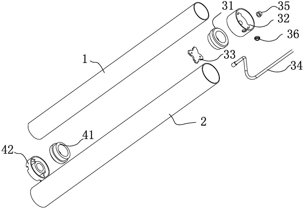
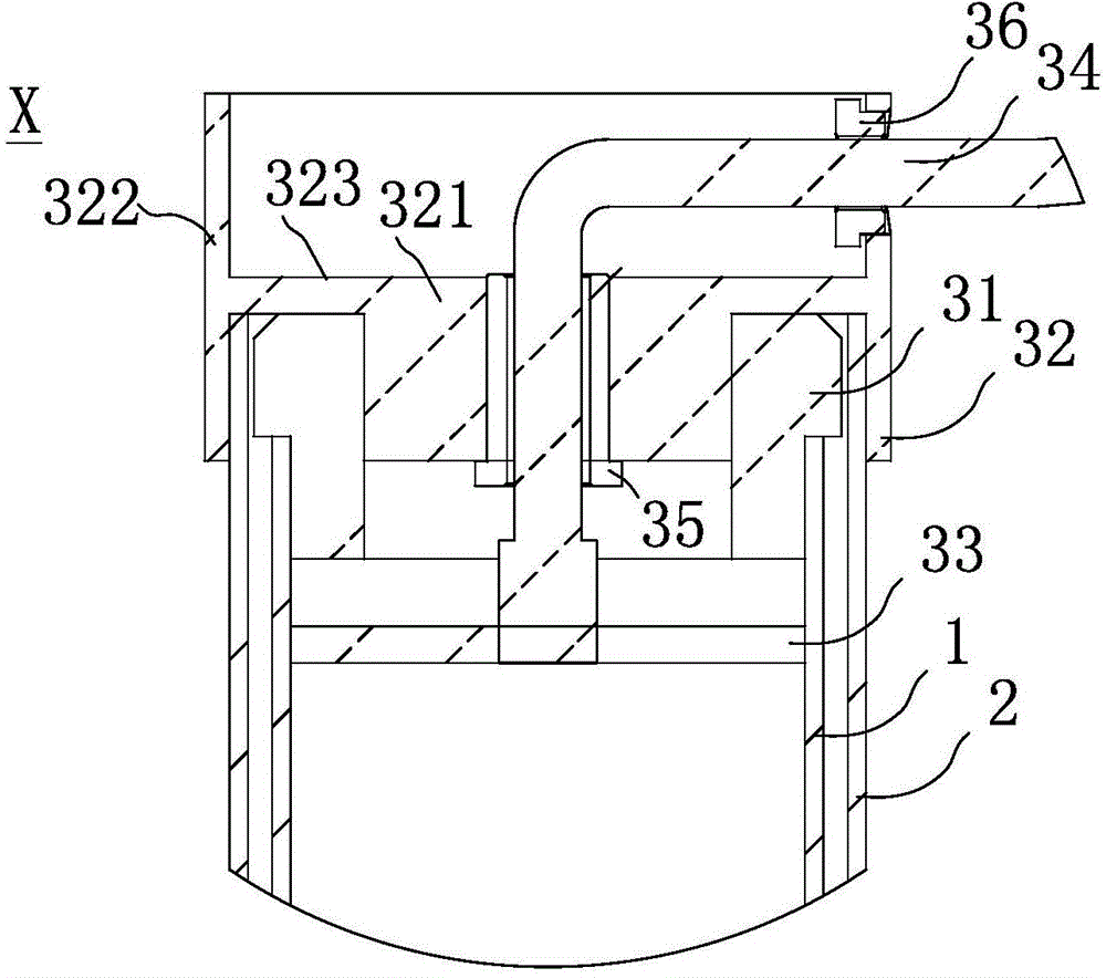
[0023] figure 1 It shows an installation section structure of a capacitive liquid level gauge, including an inner tube 1 , an outer tube 2 coaxially sheathed on the inner tube 1 , and fixing the connecting bottom and connecting head of the inner tube 1 a...


PUM


Abstract

The invention discloses an installing structure of an electric capacity type liquidometer. The installing structure comprises an inner pipe, an outer pipe coaxially sleeving the inner pipe, a connecting bottom and a connecting head part which are used for fixing the inner pipe and the outer pipe, wherein the connecting head part comprises an insulating sleeve, a positioning base, a conducting sheet used for conducting a signal on the inner pipe, and a cable wire connecting the conducting sheet, wherein the insulating sleeve is provided with a thin part and a thick part, the thin part of the insulating sleeve is inserted into the inner wall of the inner pipe and is connected with the inner wall of the inner pipe, a circulating gap is formed between the thick part of the insulating part and the inner wall of the outer pipe; the positioning base is used for clamping and fixing the insulating sleeve and the outer pipe and comprises an inner ring and an outer ring which are integrally formed, and a first communicating connecting part for connecting the inner ring and the outer ring, the inner ring is inserted into the inner wall of the insulating sleeve and is connected with the inner wall of the insulating sleeve, the outer ring tightly sleeves the outer wall of the outer pipe and is fixedly connected with the outer wall of the outer pipe, and the cable wire extends out from the positioning base through a threading part of the inner ring. The inner pipe is stably connected with the outer pipe, so that a connecting structure is small in interference to the liquidometer, and is convenient to install.

Description

technical field [0001] The invention relates to a liquid level meter which determines the liquid level through the capacitance change between the inner pipe and the outer pipe, more specifically its installation structure. Background technique [0002] The metal inner tube and the outer tube of the capacitive liquid level gauge are insulated to form a capacitor. When the liquid level rises between the inner tube and the outer tube, the medium between the two tubes changes so that the generated capacitance changes accordingly. The capacitance determines the corresponding liquid level height. In a common capacitive liquid level gauge, the connection structure connecting the inner tube and the outer tube is formed by welding a conductive sheet on the inner tube, connecting the cable to the conductive sheet, and then connecting the insulating sleeve to the inner tube, and then using the inner tube The locking ring fixes the insulating sleeve, the connecting piece is fixed on th...

Claims


Application Information

Patent Timeline
Patent Type & Authority Applications(China)
IPC IPC(8): G01F23/26
Inventor 张伟张磊
Owner SHANGHAI RENYWELL TECH
Learn More