A photoelectric cell adjustment device for laser gyroscope light combination assembly
A laser gyro and adjustment device technology, applied to measuring devices, instruments, etc., to achieve the effect of large working space, simple structure and good operability
- Summary
- Abstract
- Description
- Claims
- Application Information
AI Technical Summary
Problems solved by technology
Method used
Image


Examples
Embodiment 1
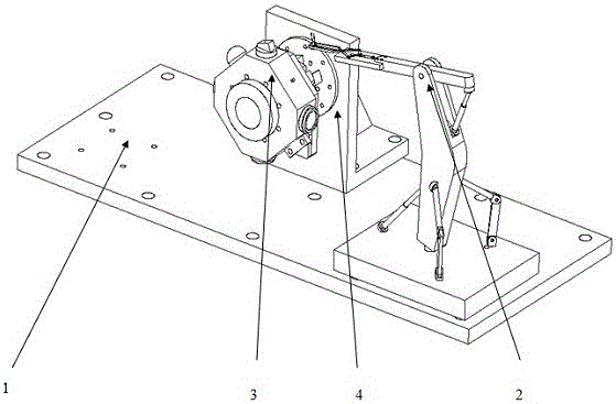
[0026] control figure 1 , This photocell adjustment device for laser gyro light combining assembly includes an optical platform (1), a photocell adjustment mechanism (2), a laser gyro shaking device (4) and an optical element to be assembled in the laser gyro light combining assembly. (3), the photocell adjustment mechanism (2) is installed on the right side of the optical platform (1), the laser gyro shaker device (4) is installed on the left side of the optical platform, and the optical element (3) to be assembled in the laser gyro light-combining assembly The resonant cavity (5) in the above is installed on the laser gyro shaker device (4), and the plane mirror (6) and the light combining prism (7) of the optical element (3) to be assembled in the laser gyro light combining assembly are placed in the resonant cavity (5). ), there are linear drive rods (20, 33) in the photocell adjustment mechanism (2) combined with the rotary drive rods (16, 25) to drive its movement and re...
Embodiment 2
[0027] Embodiment 2: This embodiment is basically the same as Embodiment 1, and the special features are as follows:
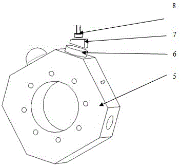
[0028] control figure 1 , 2 , the optical element (3) to be assembled in the laser gyro light combining assembly is composed of a resonant cavity (5), a plane mirror (6), a light combining prism (7) and a photocell (8). The plane mirror (6) ) is placed horizontally at the laser beam exit port of the laser gyro (5), the light-combining prism (7) is placed horizontally on the plane mirror (6), and the photocell (8) is clamped by the photocell clamping mechanism during assembly. The movement plane of (8) is parallel to the inclined plane of the light combining prism (7), and the resonant cavity (5) is installed on the laser gyro shaking device (4).
[0029] control figure 1 , 3 , the photocell adjustment mechanism comprises a base plate (9), a three-dimensional rotation mechanism (10), a one-dimensional rotation mechanism (11) and a photocell clamping mechani...
Embodiment 3
[0034] Embodiment 3: This embodiment is basically the same as Embodiment 1, and the special features are as follows:
[0035] control figure 1 , 2 , 3, 4, 5, 6, the photocell (8) is clamped by the photocell clamping mechanism (12), and the photoelectric cell is controlled by the linear drive rod (44) in the photocell clamping mechanism (12). The loosening and clamping of the tube (8); the first linear driving rod (20), the first rotary driving rod (25) and the second rotary driving rod (16) in the photocell adjustment mechanism (2) are controlled by linkage The rotation of the photocell clamping mechanism (12) around the three coordinate axes is realized, thereby realizing the rotation of the photocell (8) around the three coordinate axes; the photocell clamping mechanism (12) is realized by controlling the second linear driving rod (33). ) translational movement, thereby realizing the translational movement of the photocell (8), and controlling the first linear driving rod ...
PUM
 Abstract
Description
Claims
Application Information
 - R&D
- Intellectual Property
- Life Sciences
- Materials
- Tech Scout
- Unparalleled Data Quality
- Higher Quality Content
- 60% Fewer Hallucinations
Browse by: Latest US Patents, China's latest patents, Technical Efficacy Thesaurus, Application Domain, Technology Topic, Popular Technical Reports.
© 2025 PatSnap. All rights reserved.Legal|Privacy policy|Modern Slavery Act Transparency Statement|Sitemap|About US| Contact US: help@patsnap.com