
Wedge claw type stepless variable-speed mechanism and transmission system

A technology of continuously variable speed change mechanism and speed change mechanism, which is applied in transmission devices, friction transmission devices, mechanical equipment, etc., can solve the problems of high noise, large volume, and easy loss of transmission parts.

Inactive Publication Date: 2015-04-29
孙晓雁 +2
View PDF4 Cites 2 Cited by
  • Summary
  • Abstract
  • Description
  • Claims
  • Application Information

AI Technical Summary

Problems solved by technology

[0006] 1. Functional transmission efficiency is low, mostly no more than 0.85
[0007] 2. The speed ratio range is limited, most of which do not exceed 6
[0008] 3. At the same power and torque transmission, its volume, weight, and occupied space are larger than ordinary reducers, and it is very limited in applications that require large torque and small volume, that is, the scope of use is limited.
[0009] 4. Most of them cannot adapt to large impact loads
[0010] 5. The speed adjustment needs to overcome certain resistance, especially in the load state, so the speed adjustment takes a long time and the response is slow
[0011] 6. Due to the large power loss, the mechanism is prone to heat, and the transmission parts are prone to loss
[0012] 7. Generally, there is a lot of noise
[0014] To sum up, when the mechanical continuously variable transmission mechanism in the prior art and this type of mechanical continuously variable transmission mechanism are applied in the transmission system, the useless power consumption is large, the functional transmission efficiency is low, the speed ratio range is small, the overall mass is large, Large volume, loud noise during use and small application range

Method used


Image

  • Wedge claw type stepless variable-speed mechanism and transmission system
  • Wedge claw type stepless variable-speed mechanism and transmission system
  • Wedge claw type stepless variable-speed mechanism and transmission system

Examples


Embodiment Construction

[0042] Below in conjunction with accompanying drawing and embodiment the present invention will be further described:

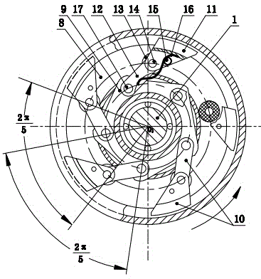
[0043] See attached Figures 1 to 7 , the wedge-claw type continuously variable transmission mechanism in the figure includes a fixed central shaft 1; where:

[0044] There is a square shaft section on the fixed central shaft 1, and a rectangular slider frame 4 is set on the square shaft section, and the rectangular slider frame 4 slides up and down at the square shaft section under the action of an external force; the rectangular slider frame 4 The outer cover is equipped with a square hole frame plate 5, and the square hole frame plate 5 slides left and right outside the rectangular slider frame 4 under the action of external force; a small eccentric sleeve 2 is set on the fixed central axis 1 close to the power input end 19 of the square shaft section The small eccentric sleeve 2 is covered with a large eccentric sleeve 3 matching the small eccentric slee...


PUM


Abstract

The invention relates to a stepless variable-speed mechanism and a transmission system, in particular to a wedge claw type stepless variable-speed mechanism. The wedge claw type stepless variable-speed mechanism comprises a fixed center shaft, wherein the fixed center shaft is provided with a dual-offset center regulating mechanism, a vector displacement limiting mechanism, a wedge claw type primary variable-speed mechanism and a wedge claw type secondary variable-speed mechanism; and the structure of a wedge claw subassembly in the wedge claw type primary variable-speed mechanism is the same with that of a wedge claw subassembly in the wedge claw type secondary variable-speed mechanism. The transmission system with the wedge claw type stepless variable-speed mechanism comprises a fixed center shaft, the wedge claw type stepless variable-speed mechanism, a primary planetary moving shaft wheel train and a secondary planetary moving shaft wheel train; and the wedge claw type stepless variable-speed mechanism is arranged between an inputting belt pulley and an outputting belt pulley on the fixed center shaft. Owing to the structure, the transmission efficiency is quite high, a speed ratio range is quite wide, the weight is light, the size is small, and requirements on large torque and small size can be met. The transmission system has the advantages that the transmission system can bear large impulsive load, and is small in speed regulating resistance, high in stability, low in power loss, low in heating, small in noise and wide in application range.

Description

technical field [0001] The invention relates to a continuously variable transmission mechanism and a transmission system, in particular to a wedge-claw type continuously variable transmission mechanism and transmission system with low power consumption, high transmission efficiency, small mass, small volume, low noise and expanded application range. Background technique [0002] The general mechanical continuously variable transmission mechanism is classified according to its working mode, mainly including friction type and meshing type. [0003] The friction type continuously variable transmission mechanism utilizes the friction force generated between the transmission parts under the action of pressure to realize power transmission, and realizes the speed change by changing the diameter ratio relationship between the transmission parts. Due to the relative motion between the transmission parts of this kind of transmission in the working state of force, and a certain surfac...

Claims


Application Information

Patent Timeline
Patent Type & Authority Applications(China)
IPC IPC(8): F16H15/00F16H37/12
CPCF16H15/00F16H37/12
Inventor 孙晓雁杨序李先明
Owner 孙晓雁
Learn More