
Connecting component of curtain wall system

A technology for connecting components and curtain walls, which is applied to building components, walls, building structures, etc. It can solve the problems of small adjustable range of back bolt components, high assembly precision, and high labor costs, so as to ensure occupational health and reduce material consumption. , the effect of less material consumption

Inactive Publication Date: 2015-04-29
邱建平 +1
View PDF0 Cites 0 Cited by
  • Summary
  • Abstract
  • Description
  • Claims
  • Application Information

AI Technical Summary

Problems solved by technology

The safety of the stone curtain wall installed by this method is relatively better, but because the position of the back bolt assembly on the stone slab is fixed, the adjustable range of the back bolt assembly is very small, requiring high assembly accuracy, and the steel frame of the stone curtain wall is very difficult. It is difficult to meet its installation accuracy. Therefore, there are few stone curtain wall projects that are completely installed with back bolt components. In some projects, while using back bolt components, in order to ensure the smooth construction of the project, a large number of metal pendants are also used to assist the installation.
Moreover, the stone curtain wall constructed using this method has high material consumption, high technical requirements, and high labor costs, resulting in high cost of the entire project and less use

Method used


Image

  • Connecting component of curtain wall system
  • Connecting component of curtain wall system
  • Connecting component of curtain wall system

Examples


Embodiment Construction

[0028] The technical characterictic of the present invention and function are described in detail below by accompanying drawing:

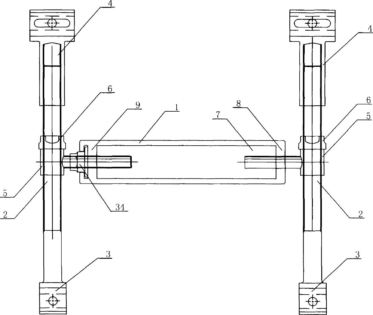
[0029] From figure 1It can be seen from the figure that the connecting member is H-shaped as a whole, with a straight web beam 1 in the middle, and the web beam 1 is a hollow member with a middle cavity of 7, and a sealing C-shaped member 9 is arranged at the left end of the web beam 1. A sealing end plate 8 is provided at the right end. A T-shaped member 5 is assembled on the left and right sides of the web beam 1, and the abdominal end screws of the T-shaped member 5 extend into the middle cavity 7 of the web beam 1, and a flange nut is assembled in the C-shaped member 9 on the left side of the web beam 1 34. The left and right spars 2 are all made up of screw rods 3 and tube nut members 4 .

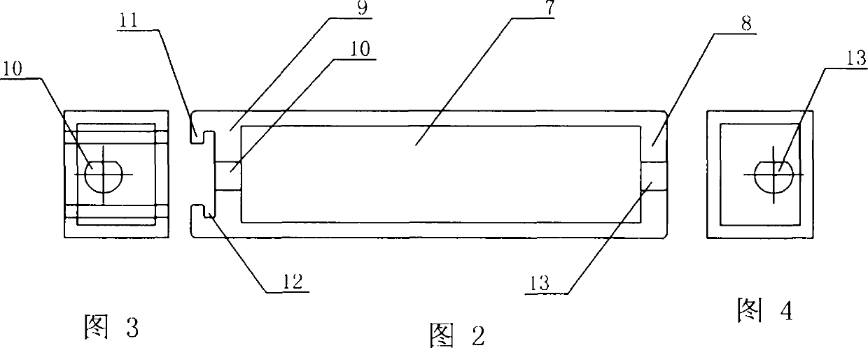
[0030] control figure 1 , figure 2 , Figure 10 and Figure 12 It can be seen that an oblate hole 10 is provided on the web of the C-shaped member ...


PUM


Abstract

Disclosed is a connecting component used for directly assembling a curtain wall board on a curtain wall vertical frame. The connecting component comprises a hollow straight web girder and two wing beams, wherein the two wing beams are connected with the web girder through T-shaped components. A C-shaped component is arranged at one end of the web girder, flange nuts are mounted at the tops and the bottoms of the two wing beams, a wing plate of one flange nut is clamped by a groove of the C-shaped component, a web plate of the C-shaped component is provided with a hole which a threaded rod penetrates through, and when the corresponding flange nut is screwed, the threaded rod mounted on the corresponding flange nut and in the hole of the web plate of the C-shaped component can be adjusted to go in and out, so that the three-directional adjusting function is achieved. The connecting component has the advantages that the construction technology content is low, accurate adjustment of the relative position between the curtain wall board and the curtain wall vertical frame is conveniently achieved, and due to the fact that the connecting component is a finished product manufactured by a factory, quality is reliable; controllability of construction quality is good, and material consumption is low; the quantity of garbage on the construction site is small, dust pollution caused in a curtain wall board on-site cutting and hole forming process and occupational diseases of construction workers do not exist, environmental protection is better achieved, and the occupational health of the construction workers is effectively guaranteed.

Description

technical field [0001] The invention relates to a connecting member of a curtain wall system, in particular to a connecting member which plays a connecting role between a curtain wall plate and a curtain wall vertical stile, and directly assembles the curtain wall plate on the curtain wall vertical stile. For the curtain wall system using this connection component, the corresponding nut on the connection component is screwed, and the curtain wall panel can realize three-way large-scale translation and rotation adjustment on the stile. Background technique [0002] Building curtain walls have been continuously improved and developed during the use of more than 30 years. Glass curtain walls and metal curtain walls have matured in technology due to their early use. Although stone curtain walls have been developed for a long time, they are still used. The metal pendant hanging installation and the back bolt component hanging method, due to the backward technical means, lead to s...

Claims


Application Information

Patent Timeline
Patent Type & Authority Applications(China)
IPC IPC(8): E04B2/88
Inventor 邱建平
Owner 邱建平
Learn More