
Bridge telescopic device anchoring structure

A telescopic device and anchoring structure technology, applied in bridges, bridge parts, bridge materials, etc., to achieve the effect of improving installation efficiency, improving service life, and reliable anchoring

Active Publication Date: 2015-04-29
GUIZHOU TRANSPORTATION PLANNING SURVEY & DESIGN ACADEME
View PDF9 Cites 1 Cited by
  • Summary
  • Abstract
  • Description
  • Claims
  • Application Information

AI Technical Summary

Problems solved by technology

[0010] In view of this, the object of the present invention is to provide an anchoring structure for bridge expansion devices, which can solve the problems of poor anchoring performance, difficult installation and unsatisfactory service life of bridge modular expansion devices in the prior art, so as to overcome the existing Insufficient technology, so as to prolong the service life of the bridge modular expansion device, avoid the safety problem of driving on the bridge caused by the damage of the expansion device, and improve the service level of the highway bridge

Method used


Image

  • Bridge telescopic device anchoring structure
  • Bridge telescopic device anchoring structure

Examples


Embodiment Construction

[0021] The present invention will be described in detail below with reference to the accompanying drawings and examples.

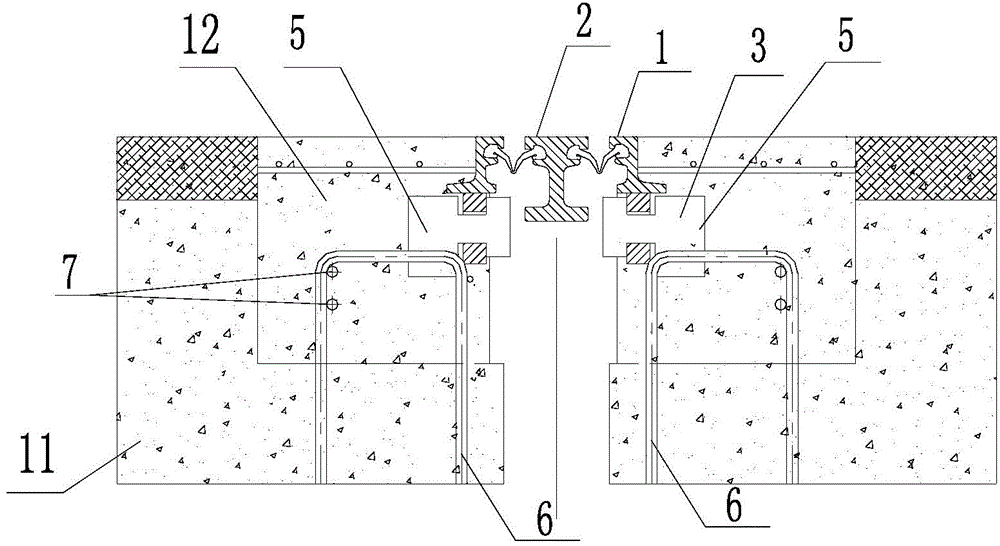
[0022] The invention provides an anchoring structure of a bridge telescopic device, comprising: a side beam 1, a connecting steel plate 3, an anchoring steel plate 5, a pre-embedded steel bar 6, a crossing steel bar 7, a U-shaped anchoring steel bar 8, a supporting beam box 9 and a displacement rod Box 10;

[0023] The connecting steel plate 3 is a rectangular plate structure, and a rectangular through hole is provided on its upper and lower surfaces;

[0024] The anchoring steel plate 5 is a plate-shaped structure, which is divided into a T-shaped part and a rectangular part, wherein the vertical part of the T-shaped part and the side length of the rectangular part are fixed as an integrated structure;

[0025] The connection relationship is as follows: the connecting steel plate 3 is set on the side beam 1 of the telescopic device, and the connecting st...


PUM


Abstract

The invention discloses a bridge telescopic device anchoring structure, which belongs to the technical field of bridge structure telescopic devices, and comprises a side beam, a connecting steel plate, an anchoring steel plate and an embedded bar, wherein the connecting relationship is as below: the connecting steel plate is arranged on the side beam and is parallel to the side beam; the anchoring steel plate penetrates through a rectangular through hole of the connecting steel plate; the anchoring steel plate can freely move along the connecting steel plate through the cooperation of a T-shaped vertical part of the anchoring steel plate and the rectangular through hole of the connecting steel plate; the anchoring steel plate is welded with the embedded bar. According to the bridge telescopic device anchoring structure, free telescoping can be realized, the service life of the modular telescopic device is prolonged, and the safety problem of driving a car on a bridge caused by the damage of the telescopic device is avoided.

Description

technical field [0001] The invention belongs to the technical field of expansion devices for bridge structures, and in particular relates to an anchoring structure for expansion devices for bridges. Background technique [0002] With the development of my country's transportation construction, the proportion of bridge engineering in expressway is constantly increasing. As the main accessory component of bridge, bridge expansion device is one of the key structures to ensure the safety of bridge operation and the smooth flow of highway. Among them, the modular expansion device is a kind of expansion device that is widely used at present. However, the current situation of the use of the existing modular expansion device shows that the damage phenomenon of the expansion device is very prominent, and the frequency of replacement is frequent, which brings safety hazards to the highway operation and society. Economic losses. The damage form of the modular expansion device is as fo...

Claims


Application Information

Patent Timeline
Patent Type & Authority Applications(China)
IPC IPC(8): E01D19/06
CPCE01D19/062E01D2101/30
Inventor 杜镔凌桂香谭捍华张世娟袁馨李少娜
Owner GUIZHOU TRANSPORTATION PLANNING SURVEY & DESIGN ACADEME
Learn More