Subframe for a motor vehicle

A technology for subframes and motor vehicles, which is applied to power units, vehicle components, substructures, etc., can solve problems such as being unable to be utilized or making full use of mass production, etc.

Active Publication Date: 2015-04-29
AUDI AG
View PDF6 Cites 0 Cited by
  • Summary
  • Abstract
  • Description
  • Claims
  • Application Information

AI Technical Summary

Problems solved by technology

[0006] Disadvantages identified here are: Depending on the configuration and power plant, cross supports or reinforcements have to be provided accordingly, which results in larger structural parts having to be produced in many variants, thus not being able to take full advantage of the advantages of mass production
These spaces cannot be utilized due to the extension directions of different power units

Method used


Image

  • Subframe for a motor vehicle
  • Subframe for a motor vehicle
  • Subframe for a motor vehicle

Examples


Embodiment Construction

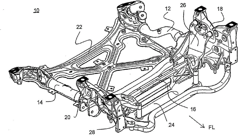
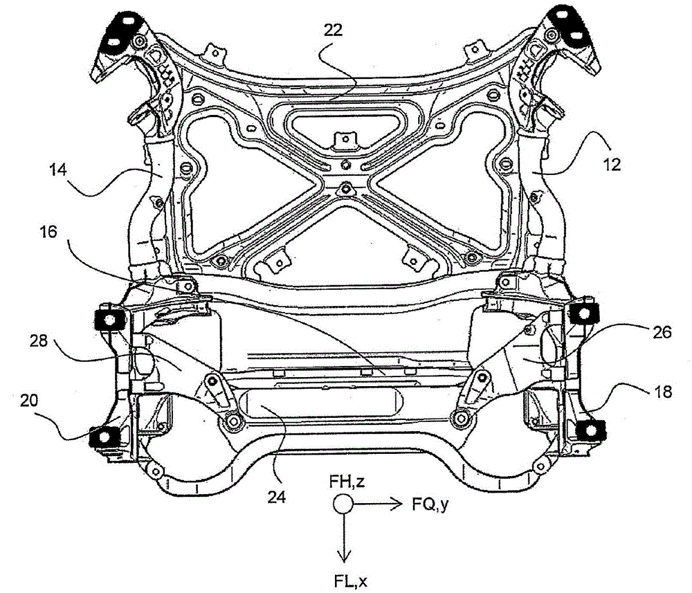
[0028] figure 1 with figure 2 A subframe for a motor vehicle is shown, generally designated by the reference number 10 .

[0029] The subframe 10 essentially has a first longitudinal member 12 oriented in the vehicle longitudinal direction FL, a second longitudinal member 14 oriented in the vehicle longitudinal direction FL, and a cross member 16 extending in the vehicle transverse direction FQ.

[0030] The two longitudinal beams 12 , 14 and the transverse beam 16 are fixedly connected to one another via first and second cast joints 18 , 20 . In addition to the cross member 16 , the subframe 10 also has a reinforcement structure 22 and a thrust area 24 as further transverse structures.

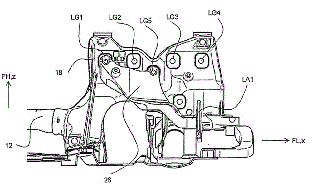
[0031] to accommodate figure 1 In the power unit, which is not shown for the sake of clarity, there are a plurality of casting joints 18, 20, especially made of image 3 Bearing connection points LG1 , LG2 , LG3 , LG4 and LG5 are shown for fastening the engine mount.

[0032] In additio...


PUM


Abstract

A subframe for a motor vehicle includes at least one transverse structure oriented in a transverse direction of the vehicle, a first and a second longitudinal member oriented in a longitudinal direction of the vehicle and connected to the at least one transverse structure by respective first and second cast joints respectively arranged between the first longitudinal member and the at least one transverse structure and the second longitudinal member and the at least one transverse structure, the first and second cast joints each having bearing connection points for fastening an engine bearing. The subframe also includes connection parts, one of which is provided for each of the first and second cast joints, the connection parts each having at least one other bearing connection point for fastening the engine bearing, and multiple bearing sites via which the connection parts are fastenable on the at least one transverse structure and on the bearing connection points of the first and second cast joints.

Description

technical field [0001] The invention relates to a subframe for a motor vehicle of the type according to the preamble of claim 1 . Background technique [0002] Such subframes for motor vehicles are sufficiently known in the prior art and are generally formed by two cast joints spaced apart from one another, which are connected to one another by means of cross members and / or reinforcements. In addition, the subframe has longitudinal members, which are connected not only to the cast joints but also to the body. These cast joints or the side members have corresponding connection points for mounting the chassis control arms. For receiving / fixing the power unit (powertrain), so-called engine mounts are used. These bearings serve to decouple vibrations caused by the drive unit and to absorb forces and moments that occur during driving operation. These engine supports can be fastened to corresponding support connection points of the subframe. A subframe of this type for a motor...

Claims


Application Information

Patent Timeline
Patent Type & Authority Applications(China)
IPC IPC(8): B62D21/11B62D21/02
CPCB62D21/11B60K5/12B60K5/1283B62D21/02
Inventor C·伊萨基维施S·施布莱克
Owner AUDI AG
Why Eureka
Try Eureka