Double-positioning cold-ironing system

A double-positioning, cold foiling technology, applied in printing, rotary printing presses, printing presses, etc., can solve the problems of inability to manufacture, no technical solution proposed, and insufficient utilization of metal coating, and achieve the effect of saving cold foiling

Inactive Publication Date: 2015-04-29
XIAMEN QIANRUN TECH
View PDF7 Cites 10 Cited by
  • Summary
  • Abstract
  • Description
  • Claims
  • Application Information

AI Technical Summary

Problems solved by technology

[0003] The disadvantages of the current single-position cold stamping system are: 1. The cold stamping film can only be used once, and the metal coating between two adjacent hot stamping positions on the cold stamping film has not been fully utilized and can only be discarded together with the used cold stamping film waste. throw away
2. It is not possible to transfer trademarks such as laser patterns (14) and other complete fixed positions designed in advance to the designated positions on the printed matter
[0004] Two patent applications including Chinese patent CN201151231Y "Multi-color group positioning cold foil transfer printing machine" and Chinese patent CN101480867A "Method for realizing multi-color group positioning cold foil transfer printing" are documents submitted by the same applicant. These two patent application documents, Only the preliminary idea of ​​the dual-positioning cold ironing system was proposed, neither a specific practical technical solution nor the working principle of the dual-positioning system was proposed, and those skilled in the art could not manufacture its "multi-color group positioning system" based on its application documents. Cold Foil Transfer Printing Machine
The applicant once ordered the "multi-color group positioning cold stamping transfer printing machine (CN201151231Y)" from the applicant several years ago, but the applicant himself has not been able to produce an available "multi-color group positioning machine" so far. Cold Foil Transfer Printing Machine

Method used


Image

  • Double-positioning cold-ironing system
  • Double-positioning cold-ironing system
  • Double-positioning cold-ironing system

Examples


Embodiment 1

[0037] 1. Design and installation of mechanical and electrical systems.

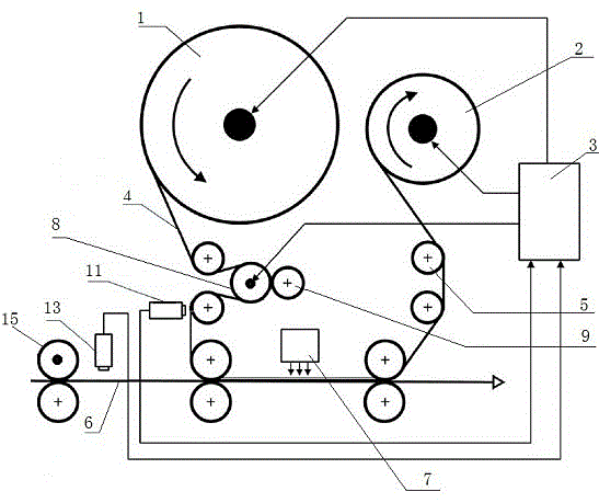
[0038] In advance, according to the customer's needs, survey and map the installation position of the printing machine equipped with the positioning cold ironing system of the present invention (including the installation method of fixed position and moving guide rail). It is required to survey and map the installation position of the synchronous encoder (15) and the installation position of the electric eye B (13) for reading the printed matter cursor (12).

[0039] Design and install the base, guide rail and bracket according to the location and size of the survey.

[0040] Overall assembly after machining, electrical system assembly.

[0041] The positioning cold ironing system of the present invention is powered on and tested before leaving the factory.

[0042] Installation to customer's factory.

[0043] Install the dual-position cold stamping system of the present invention on the printing mach...

Embodiment 2

[0054] see figure 1 As in the previous example, the dual-position cold ironing system of the present invention is designed and manufactured, and installed on the printing press according to the position previously surveyed and mapped. Connect the synchronous encoder (15) to the main drive shaft of the printing press to detect the speed of the printing press. The electric eye B (13) for reading the printed matter cursor (12) is installed on the existing flexo self-adhesive label printing machine.

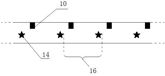
[0055] Such as image 3 As shown, the printed matter (6) ready to be printed is designed. The printed matter (6) is a rectangular rounded self-adhesive label of 104mm×64mm. The typesetting length y (17) of a label is 108.03mm, and the same position on the edge of each label A 6mm×4mm black print cursor (12) is printed, and the distance between the cursors is also 108.03mm. The printed matter (6) is printed with an existing flexographic self-adhesive label printing machine.

[00...

Embodiment 3

[0062] see figure 1 As in the previous example, the dual-position cold ironing system of the present invention is designed and manufactured, and installed on the printing press according to the position previously surveyed and mapped. Connect the synchronous encoder (15) to the main drive shaft of the printing press to detect the speed of the printing press. The electric eye B (13) for reading the printed matter cursor (12) is installed on the existing flexo self-adhesive label printing machine.

[0063] Such as image 3 As shown, the printed matter (6) to be printed is designed. The printed matter (6) is a rectangular rounded self-adhesive label of 104mm×64mm, the label spacing y (17) is 108mm, and a 6mm label is printed at the same position on the edge of each label ×4mm black print cursors (12), the distance between the cursors is also 108mm. The printed matter (6) is printed with an existing flexographic self-adhesive label printing machine.

[0064] Such as Figure ...


PUM


Abstract

The invention provides a double-positioning cold-ironing system which comprises a displacement roller driven by a motor, a compression roller of the displacement roller, an electric eye A reading a cold-ironing film cursor and an electric eye B reading a presswork cursor. The electric A and the electric B are respectively communicated with a computer control unit and respectively transmit the read cursor signals to the computer control unit. The computer control unit controls the motor and drives the displacement roller to move ahead or backward according to the difference value between the two cursor signals so that fine tuning and calibration can be conducted. The double-positioning cold-ironing system can use the cold-ironing film repeatedly for many times and transfer the whole trademarks like laser patterns designed in advance to the specified fixed position on the presswork so that positioning cold ironing can be realized.

Description

technical field [0001] The invention belongs to the technical field of cold foil printing, and specifically relates to a positioning cold foiling system for overlapping and registering each complete laser pattern (the first pattern) on the cold foil film and each glue pattern (the second pattern) on the printed matter , because the two patterns are overlapped and registered, so it belongs to the double positioning cold perm system. Background technique [0002] The current cold foil system is a single-position cold foil system, which can only transfer the metal coating (incomplete pattern) on the cold foil film to the designated position on the printed matter. Such as Figure 5 As shown, it includes an unwinding unit (1), a winding unit (2) and a computer control unit (3). The cold film (4) is sent out from the unwinding unit (1), wound around the roller (5) and printed on the printed matter. The local glue pattern (20) on (6) is bonded → UV light curing → peeling off → tra...

Claims


Application Information

Patent Timeline
IPC IPC(8): B41F16/00
CPCB41F16/00
Inventor 简镇明汪礼学陈丰良
Owner XIAMEN QIANRUN TECH
Why Eureka
Try Eureka