Bionic spine motion segment

A technology of movable joints and spine, applied in the field of bionic robots, can solve the problems of non-adjustable mechanism rigidity and insufficient energy saving

Active Publication Date: 2015-04-29
CHINA JILIANG UNIV
View PDF9 Cites 15 Cited by
  • Summary
  • Abstract
  • Description
  • Claims
  • Application Information

AI Technical Summary

Problems solved by technology

However, due to the hydraulic drive, the rigidity of the mechanism cannot be adjusted, and it is not energy-saving enough

Method used


Image

  • Bionic spine motion segment
  • Bionic spine motion segment
  • Bionic spine motion segment

Examples


Embodiment Construction

[0017] The present invention will be further described below in conjunction with the accompanying drawings and specific embodiments.

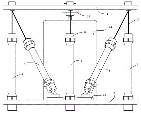
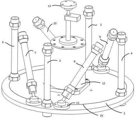
[0018] Such as figure 1 , figure 2 and Figure 4 As shown, the present invention includes upper vertebral body 1, lower vertebral body 2, first erector muscle 3, second erector muscle 4, third erector muscle 5, fourth erector muscle 6, first oblique muscle 7, second oblique muscle 8. The third oblique muscle 9, the fourth oblique muscle 10, the steel wire rope 11, the recoverable magneto-rheological damper assembly 12, the ball hinge 13, the cylinder limit bracket 14, the electric proportional valve 15, the pressure reducing valve 16, the gas Source 17 and controller 18; the first erector 3, the second erector 4, the third erector 5, the fourth erector 6, the first oblique 7, the second oblique 8, the third oblique 9 and the fourth oblique muscle 10 are pneumatic muscles, one end of the cylinder limit bracket 14 is fixed at the upper center...


PUM


Abstract

The invention belongs to the technical field of a bionic robot and especially relates to a bionic spine motion segment. The bionic spine motion segment comprises an upper vertebrae, a lower vertebrae, a first erector muscle, a second erector muscle, a third erector muscle, a fourth erector muscle, a first oblique muscle, a second oblique muscle, a third oblique muscle, a fourth oblique muscle, a steel wire rope, a reversible magneto-rheological damper component, a spherical hinge, a cylinder limit bracket, an electric proportional valve, a pressure reducing valve, an air source and a controller, wherein the upper vertebrae can realize four-freedom movement when a pneumatic muscle is driven, thus the bionic spine motion segment is flexible, clean and energy-saving; the reversible magneto-rheological damper component can be adjusted in damping, so that the moving posture of the upper vertebrae can be adjusted and the support and damping effect can be achieved; the rigidity of the bionic vertebrae can be changed by adjusting air pressure in the pneumatic muscle. The bionic spine motion segment is characterized in that the characteristics of the biological vertebrae motion segment can be better simulated and the bionic spine motion segment is innovated and expanded in function, thus the bionic spine motion segment is worth to be applied.

Description

technical field [0001] The invention belongs to the technical field of bionic robots, in particular to a bionic spinal movable segment. Background technique [0002] Legged creatures generally have strong coordination and stability when walking, running and jumping. This is not only closely related to their complex motor nervous system, but also inseparable from their perfect torso structure. Most of the current legged bionic robots are simplified modeling based on the premise of a rigid torso. In fact, the torso of a legged creature will deform flexibly during the movement to ensure the stability and stability of the creature's movement. coordination. Especially when the organism is performing strenuous movements such as running and jumping, if a purely rigid torso model is still used, the mechanical properties of the biological movement cannot be reasonably reproduced, making it difficult to further improve the research on the walking efficiency and stability of the robot...

Claims


Application Information

Patent Timeline
IPC IPC(8): B25J17/00
Inventor 王斌锐干苏鲍春雷张斌金英连
Owner CHINA JILIANG UNIV
Why Eureka
Try Eureka