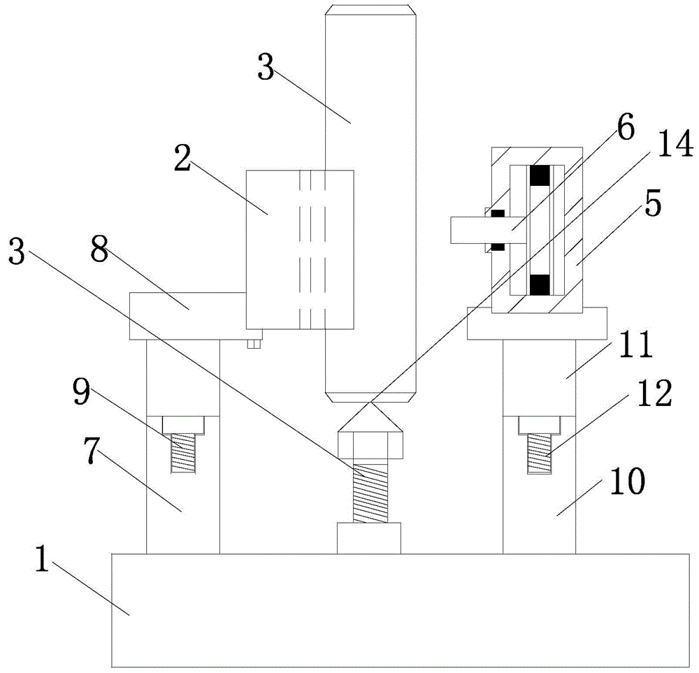
Liftable fixture for groove milling of end faces of hinge pins
A technology for fixing fixtures and shaft end faces. It is applied in the direction of clamping, positioning devices, clamping devices, etc. It can solve problems such as difficult clamping, dents on the outer surface of the pin shaft, time-consuming and labor-intensive problems, etc., to achieve firm clamping, avoid dumping, Avoid the effect of rotating and moving down
Inactive Publication Date: 2015-04-29
TERRENCE ENERGY
View PDF0 Cites 3 Cited by
- Summary
- Abstract
- Description
- Claims
- Application Information
AI Technical Summary
Problems solved by technology
[0002] At present, when milling the groove on the end face of the pin shaft, because the outer surface of the pin shaft is relatively smooth and cylindrical, it is difficult to clamp; if the general pressing block assembly is used for pressing, it needs to be pressed on the end face of the pin shaft, and the groove cannot be clamped once. After the machining is completed, re-clamping and tool setting are required, which is time-consuming and labor-intensive; while using a vise to clamp, it is easy to cause dents on the outer surface of the pin shaft, which affects the smoothness of the surface
Method used
View moreImage
Smart ImageViewing Examples
Examples
Embodiment 2
[0015] A horizontal platform 14 is arranged on the screw nail point. Because the screw tip is too sharp, not only is it easy to wear when clamping the pin shaft, but it is also easy to cause pits on the surface of the pin shaft, which affects the appearance; by setting a horizontal platform, when the screw tip contacts the pin shaft, the face-to-face The contact can effectively avoid the wear of the nail tip.
Login to View More PUM
 Abstract
The invention relates to the technical field of mechanical clamping, in particular to a liftable fixture for groove milling of end faces of hinge pins. A first limiting device, a second limiting device and a third limiting device are disposed on a base; the first limiting device comprises a 'T'-shaped first lifting device and a 'V'-shaped limiting block which is inwardly arranged at the top end of the first lifting device; a second limiting device comprises a 'T'-shaped second lifting device and a clamping device arranged at the top end of the second lifting device; the third limiting device comprises a supporting nail with the sharp end up, and the supporting nail is arranged on a transverse portion of the base. The liftable fixture for groove milling of the end faces of the hinge pins has the advantages of convenience in clamping and avoidance of influences on surface smoothness and machining.
Description
technical field [0001] The invention relates to the technical field of mechanical clamping, in particular to a fixed fixture for milling grooves on the end face of a liftable pin shaft. Background technique [0002] At present, when milling the groove on the end face of the pin shaft, because the outer surface of the pin shaft is relatively smooth and cylindrical, it is difficult to clamp; if the general pressing block assembly is used for pressing, it needs to be pressed on the end face of the pin shaft, and the groove cannot be clamped once. After the machining is completed, re-clamping and tool setting are required, which is time-consuming and labor-intensive; while using a vise to clamp, it is easy to cause dents on the outer surface of the pin shaft, which affects the smoothness of the surface. Contents of the invention [0003] The purpose of the present invention is to provide a fixed fixture for milling grooves on the end face of a liftable pin shaft which is conve...
Claims
Login to View More Application Information
Patent Timeline
 IPC IPC(8): B23Q3/08
CPCB23Q3/08B23Q2703/04
Inventor 姚保纯汪洋谢耀东杨飞
Owner TERRENCE ENERGY
- R&D Engineer
- R&D Manager
- IP Professional
- Industry Leading Data Capabilities
- Powerful AI technology
- Patent DNA Extraction
Learn More Browse by: Latest US Patents, China's latest patents, Technical Efficacy Thesaurus, Application Domain, Technology Topic, Popular Technical Reports.
© 2024 PatSnap. All rights reserved.Legal|Privacy policy|Modern Slavery Act Transparency Statement|Sitemap|About US| Contact US: help@patsnap.com


