Special cleaning equipment for tanks

A technology for equipment and tanks, applied in the field of special equipment, can solve the problems of complex and bulky structure, low cleaning efficiency, high labor intensity, etc., and achieve the effects of good cleaning effect, high operation efficiency and safety protection.

Active Publication Date: 2017-05-10
南京洁德美环境技术有限公司
View PDF8 Cites 0 Cited by
  • Summary
  • Abstract
  • Description
  • Claims
  • Application Information

AI Technical Summary

Problems solved by technology

Moreover, the manhole size of the tank car is small, and there are a large amount of toxic and harmful substances such as flammable and explosive liquids inside the tank car, so the cleaning of the inner wall of the tank car is very difficult and the operation risk factor is extremely high
[0004] At present, the cleaning of tank trucks mostly adopts the manual open cleaning method, which is labor-intensive, causes serious environmental pollution, and greatly damages the health of operators.
[0005] With the consideration of the occupational safety of operators and related regulations becoming more and more stringent, some users are currently using cleaning equipment to clean the inside of the tank car. However, because the tank car has a long oval structure, the length of both ends is much greater than the width. As a result, many technical difficulties occurred when the equipment was cleaned and entered and exited, and the cleaning quality and cleaning effect were difficult to guarantee
[0006] Due to the complex and bulky structure, low cleaning efficiency, and blind spots in cleaning equipment, it has been difficult to promote automatic machine cleaning in the field of tank cars, and manual cleaning is still the main method.

Method used


Image

  • Special cleaning equipment for tanks
  • Special cleaning equipment for tanks

Examples


Embodiment 1

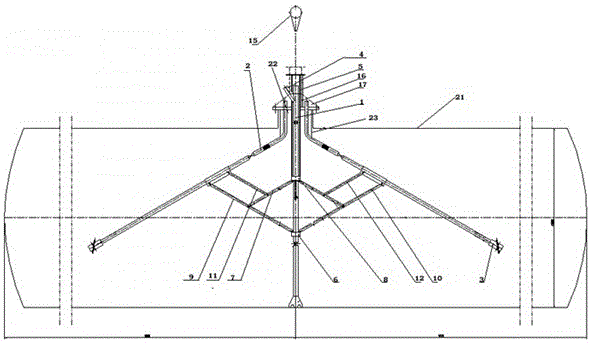
[0024] Such as figure 1 As shown, a special cleaning equipment dedicated to tanks, the tank is composed of a tank body 21, a manhole 22, and a baffle 23. The special cleaning equipment used for this tank includes a hollow middle discharge pipe 1 and a hollow water delivery pipe 2. The top end of the water delivery pipe 2 is a hose structure, and the bottom end of the water delivery pipe 2 is fixedly equipped with a tank washer 3 , the bottom end of the middle row pipe 1 is provided with a bottom hole, preferably, in this embodiment, a suction branch pipe 4 is also arranged at the side hole, and a lifting rod 5 is provided on the outer sleeve of the middle row pipe, and Corresponding to the lifting rod limit ferrule 6 arranged on the middle row pipe 1, two connecting rods are symmetrically fixed on the bottom end of the lifting rod 5, which are respectively the first connecting rod 7 and the second connecting rod 8. Two connecting rods are fixed on the end surface, which are r...

Embodiment 2

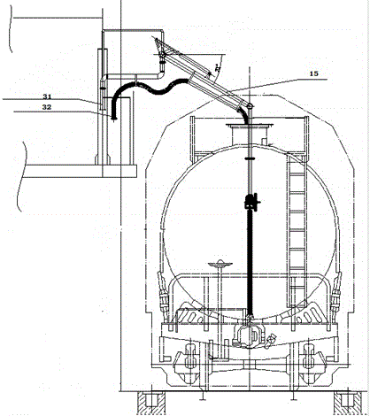
[0037] On the basis of Embodiment 1, we further disclose that an exhaust gas collection cover 17 is arranged on the upper part of the manhole, and the gas collected in the exhaust gas collection cover is directly introduced into the exhaust gas treatment device through the air guide pipe for centralized treatment.

[0038] Of course, the gas can also be left untreated according to the methods in the prior art, but since the amount of waste gas produced in the cleaning itself is relatively large, the use of a waste gas collection cover is more in line with the needs of environmental protection.

[0039] For different working conditions of the storage tank, this equipment can use "one set" mechanism, or "three sets" mechanism, or "four sets" mechanism to realize the operation.


PUM


Abstract

The invention relates to a special device, in particular to a special washing device for a tank pot. The special washing device for the tank pot aims at solving problems during the washing process of the tank pot of a special structure. The special washing device for the tank pot comprises a middle drainage pipe of a hollow structure and a hollow water conveying pipe, wherein a lifting rod sleeves the outer side of the middle drainage pipe, two connection rods are symmetrically fixed at the bottom of the lifting rod, and the two connection rods are fixed with another two connection rods fixed on the upper end face of a clamp sleeve through hinge joints. By adopting the technical scheme, pot washers of the special washing device for the tank pot can smoothly pass through manholes, and then are smoothly fed to the middle of the tank pot, and therefore the special washing device for the tank pot can guarantee that the pot washers are evenly distributed and jet water to the inner wall of the tank pot at a short distance, and then achieves strong decontamination effects, and not only is good in cleaning effect, but also is high in work efficiency, low in water consumption and low in power consumption. Simultaneously, due to the fact that the special washing device for the tank pot avoids manual pot entrance operation, and greatly improves professional security.

Description

technical field [0001] The invention relates to special equipment, in particular to a special washing equipment for tanks. Background technique [0002] Tanks are an important tool for transporting and storing liquid materials, and are widely used in transportation fields such as petroleum, chemical, and food oil. Currently common tanks include railway tank cars, road tank cars, tank containers, underground oil tanks at gas stations, and various storage tanks and storage tanks. The following uses railway tank cars as an example. [0003] In order to ensure the transportation safety of the liquid inside the tank car and its own quality, the inner wall of the tank car must be regularly cleaned during reloading. However, the structure of the tank car has great particularity. The length of the tank body is much greater than the width, and the overall structure is oblong. Moreover, the manhole size of the tank car is small, and there are a large amount of toxic and harmful subs...

Claims


Application Information

Patent Timeline
Patent Type & Authority Patents(China)
IPC IPC(8): B08B9/34B08B13/00
CPCB08B9/34B08B13/00B08B2209/027
Inventor 陈雨达陈艺伟
Owner 南京洁德美环境技术有限公司
Why Eureka
Try Eureka