
No-residual vertical type household noodle maker

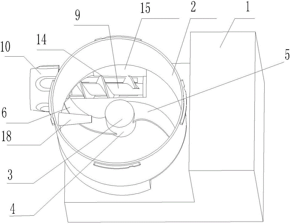
A domestic noodle machine, no residue technology, applied in dough extruder, mixing/kneading with vertical installation tools, application, etc., can solve the problem of noodle flocculation or dough residue, flocculation or dough residue, and reduce extrusion efficiency and other problems, to achieve the effect of not easy to stick to residue, easy to drive and connect, and smooth into the surface

Active Publication Date: 2015-04-29
JOYOUNG CO LTD
View PDF11 Cites 8 Cited by
  • Summary
  • Abstract
  • Description
  • Claims
  • Application Information

AI Technical Summary

Problems solved by technology

When kneading dough, the stirring rod rotates in the forward direction to mix flour and water into flocs or dough; The noodle inlet on the top of the extruding cylinder falls into the extruding cylinder, and then is extruded by the screw, but there is a problem in this method. In the early stage of extruding, due to the large amount of flour or dough, the stirring teeth are easy to crush the dough. The wadding or dough is scraped up and brought into the noodle extrusion cylinder. In the later stage of noodle extrusion, the wadding or dough becomes less, and the stirring teeth cannot scrape up the wadding or dough, or fall into the mixing cup as soon as it reaches the noodle inlet. , resulting in some flocculation or dough remaining in the mixing cup
[0005] Another example is the vertical noodle machine disclosed by the publication number CN202476367U. Because the stirring rod and the screw rod rotate differently, and the extruding cylinder is located below the stirring cup, the problem of dough residue is well solved, but the existing vertical noodle still exists. Certain problems, when kneading the dough, the stirring rod mixes the flour and water to form flocs or dough; when extruding the dough, because the reconciled flocs or dough are relatively large, it is difficult for the flocs or dough to enter the extruded dough from the noodle inlet inside the cylinder, thereby reducing the extrusion efficiency, thereby reducing the processing efficiency

Method used


Image

  • No-residual vertical type household noodle maker
  • No-residual vertical type household noodle maker
  • No-residual vertical type household noodle maker

Examples


Embodiment 2

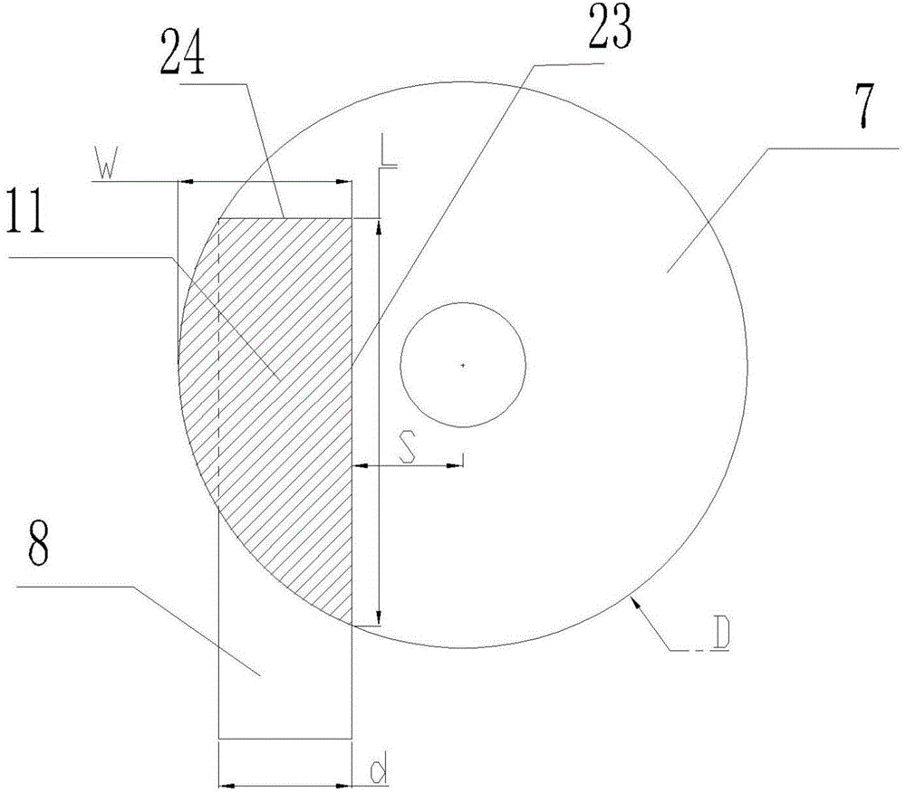
[0060] like Figure 5 As shown, the difference between this embodiment and Embodiment 1 is that the cross-section of the noodle inlet 11 is an arcuate structure, and the connection between the noodle inlet 11 and the side wall of the mixing cup 2 forms an arcuate arc edge. The side wall of the extruding barrel intersects with the bottom of the mixing cup to form a bow-shaped chord, and the two ends of the arc are respectively connected to the two ends of the chord, and the slope 15 extends downward along the arc to the material propulsion chamber 13 . The advantage of such setting is: the bow-shaped noodle inlet 11 can ensure that under the premise of the circular mixing chamber 7, the area of ​​the noodle inlet 11 is maximized, and the proportion of the stirred dough entering the noodle inlet 11 per unit time is the largest. Thereby improving the efficiency of dough feeding. In addition, the bow-shaped arc edge is also conducive to the falling of the dough. There is no dead ...

Embodiment 3

[0062] like Image 6 As shown, the difference between this embodiment and Embodiment 1 is that the mixing cup in this embodiment is square, the noodle inlet 11 is arranged along any side of the square, and the long straight side 23 is parallel to the side , and intersects the adjacent two sides. The advantage of this setting is that the noodle inlet 11 is arranged along the side of the square, so that the length of the noodle inlet 11 is maximized, thereby increasing the ratio of noodle inlet per unit time and improving the efficiency of noodle forming. The square mixing cup is disturbing. The effect of flow makes the stirring effect more fully.

Embodiment 4

[0064] like Figure 7 As shown, the difference between this embodiment and Embodiment 1 is that the stirring cup in this embodiment is a regular hexagon, the noodle inlet 11 is arranged along any side of the regular hexagon, and the long straight sides 23 are parallel intersects the side, and intersects the adjacent two sides. The advantage of such setting is: the regular hexagonal stirring cup 2 makes the strength of the stirring cup 2 high, and it is not easy to deform or vibrate during the stirring process, which reduces the vibration caused by the stirring rod 3 during the stirring process, reduces the noise, and makes The noodle machine runs more smoothly. In addition, the distance between each side and the rotation circle of the stirring rod 3 changes. Therefore, when the stirring rod 3 rotates, the side of the regular hexagon of the stirring cup can play a role in retaining the ribs and improve the flour quality. , The mixing efficiency of water, the regular hexagonal ...


PUM


Abstract

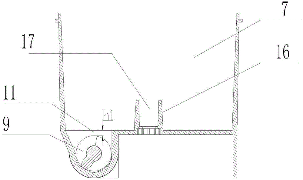
The invention discloses a no-residual vertical type household noodle maker which comprises a motor base, a motor arranged in the motor base, a stirring cup arranged above the motor base, a stirring rod and a dough extruding cylinder arranged in the stirring cup, a screw rod arranged in the dough extruding cylinder and a die head arranged on the end part of the dough extruding cylinder, wherein the dough extruding cylinder is horizontally arranged on one side below the stirring cup and consists of a material advancing cavity and an extrusion cavity, the motor drives the screw rod and the stirring rod to move, wherein a dough inlet communicated with the dough extruding cylinder is formed in the position of the bottom of the stirring cup, far away from the center, the material advancing cavity extends upwards and is intersected with the bottom of the stirring cup to form the dough inlet, and the dough inlet horizontally extends to the direction of the dough extruding cylinder along the bottom of the stirring cup, and extends to the side wall of the stirring cup. By adopting the technical scheme, the area of the dough inlet is largest, so that dough feeding is facilitated, residuals of dough in the stirring cavity can be avoided, and the stirring cavity and the stirring rod are conveniently cleaned.

Description

technical field [0001] The invention relates to the field of food processing, in particular to a residue-free vertical household noodle machine. Background technique [0002] With the improvement of living standards, food processors are becoming more and more popular among consumers, and noodle machines are becoming more and more popular among consumers. [0003] Existing noodle machines generally include horizontal noodle machines and vertical noodle machines, and all include machine bases, stirring assemblies and extruding assemblies. head. [0004] As the disclosed horizontal noodle machine with publication number CN103518792A, because the stirring rod and the screw rod rotate coaxially, and the turning radius of the stirring rod is greater than that of the screw rod. When kneading dough, the stirring rod rotates in the forward direction to mix flour and water into flocs or dough; The noodle inlet on the top of the extruding cylinder falls into the extruding cylinder, ...

Claims


Application Information

Patent Timeline
IPC IPC(8): A21C11/16A21C1/02A23L1/16A23L7/109
CPCA21C1/02A21C11/20
Inventor 王旭宁苏荣清刘健卢孟林
Owner JOYOUNG CO LTD
Learn More