Novel active front-end controller topological structure

A front-end controller and topology technology, which is applied in the direction of inverters with reversible conversion equipment, output power conversion devices, electrical components, etc. Poor characteristics and other problems, to achieve the effects of superior output characteristics, suppression of switching losses, and good modularity

Inactive Publication Date: 2015-04-22
NORTHEAST DIANLI UNIVERSITY
View PDF4 Cites 26 Cited by
  • Summary
  • Abstract
  • Description
  • Claims
  • Application Information

AI Technical Summary

Problems solved by technology

[0003] The main problems of the AFEC controller at the present stage are: 1. In the AC / DC converter link, because the traditional H-bridge converter and the 3-level NPC converter module are used at this stage, the main problems are: (1) each bridge There is a series active switch on the arm, so there is a shoot-through problem; (2) Although the equivalent frequency of the switch increases with the number of cascaded modules, the switching frequency of each module is still limited, because as the frequency increases, the dead zone The proportion of time will become larger and larger, which will lead to a decrease in the utilization rate of DC voltage; (3) MOSFETs cannot be simply used directly, because the characteristics of the parasitic diodes of high-voltage MOSFETs are very poor, thus losing the low switching loss and resistive properties of MOSFETs Advantages such as conduction characteristics and high frequency
[0004] 2. The back-end output parallel DC-DC converter adopts a 2-level / three-level DAB converter. Because it must adopt a closed-loop control phase shift angle to ensure the voltage output characteristics, there are problems such as low-load stability control; at the same time Resonant converters based on frequency conversion control can also be used, such as series resonant converters, etc., but the realization of multi-module frequency conversion control has certain complexity

Method used


Image

  • Novel active front-end controller topological structure
  • Novel active front-end controller topological structure
  • Novel active front-end controller topological structure

Examples


Embodiment Construction

[0019] The above and other technical features and advantages of the present invention will be described in more detail below in conjunction with the accompanying drawings.

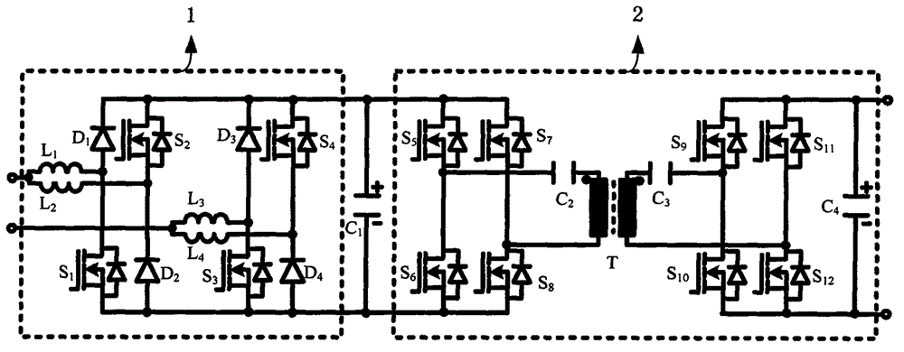
[0020] see figure 1 As shown, the present invention is a novel AFEC topology based on the combination of dual buck / boost full-bridge converters and CLLC resonant converters.

[0021] The first power converter 1 is a first bridge arm composed of the first power diode D1, the first power switch tube S1, and the first reactor L1, the second power diode D2, the second power switch tube S2, and the third reactor The second bridge arm composed of the device L2, the third bridge arm composed of the third power diode D3, the third power switch tube S3, the third reactor L3 and the fourth power diode D4, the fourth power switch tube S4, the fourth reactance The fourth bridge arm composed of device L4.

[0022] The first bridge arm is composed of the first power diode D1 and the first power switch tube S1 connecte...


PUM


Abstract

The invention relates to a novel active front-end controller topological structure which comprises a dual buck/boost type AC/DC converters and a DC CLLC resonant converter. The novel active front-end controller topological structure is characterized in that the dual buck/boost type AC/DC converters and the DC CLLC resonant converter serve as core constituent parts of an AFEC body topological structure and are formed by combining an input series-connection mode and an output parallel-connection mode, and mutual power conversion between a medium-voltage alternating-current power distribution network and a low-voltage alternating-current power distribution network is achieved by utilizing a power electronic technology and a high-frequency isolation technology. In addition, voltage regulation control is conducted on a low-voltage direct-current side busbar to achieve power balance of the medium-voltage alternating-current side and the low-voltage direct-current side. Functions of reactive compensation, active filtering, bidirectional power conversion and the like can be achieved according to different actual requirements. The novel active front-end controller topological structure can fully play the potential value of an active front-end controller, has high reliability and system efficiency and good modularity and meets different voltage class requirements.

Description

technical field [0001] The invention relates to the field of AFEC topological structures, in particular to a novel AFEC topological structure based on the combination of double buck / boost full-bridge converters and CLLC resonant converters. Background technique [0002] Active Front-End Controller (AFEC) in intelligent general-purpose transformer is a device that uses power electronics technology and high-frequency isolation technology to realize power conversion between medium-voltage AC distribution network and low-voltage DC distribution network. The essential function of the controller is to regulate and control the voltage of the low-voltage DC side bus to achieve the power balance between the medium-voltage AC side and the low-voltage DC side; at the same time, according to different actual requirements, it can achieve reactive power compensation, active filtering and power bidirectional conversion and other functions. It can conveniently provide a DC interface for ne...

Claims


Application Information

Patent Timeline
Patent Type & Authority Applications(China)
IPC IPC(8): H02M7/72H02J5/00
CPCH02M7/797H02J5/00H02M3/335
Inventor 刘闯蔡国伟
Owner NORTHEAST DIANLI UNIVERSITY
Why Eureka
Try Eureka