
Air conditioner

An air conditioner and outdoor heat exchanger technology, applied in the field of air conditioning, can solve problems such as complex refrigeration system design, low temperature drop of outdoor electrical control, poor heat dissipation, etc., to improve reliability and safety, and avoid temperature drop too low to prevent the effect of condensed water

Active Publication Date: 2015-04-22
GD MIDEA AIR-CONDITIONING EQUIP CO LTD
View PDF6 Cites 11 Cited by
  • Summary
  • Abstract
  • Description
  • Claims
  • Application Information

AI Technical Summary

Problems solved by technology

However, in high-temperature outdoor environments, this heat dissipation method is poor in heat dissipation. The usual method is to reduce the operating frequency of the compressor and reduce the heat generated by the electronic control to ensure the normal operation of the air conditioner.
It greatly affects the cooling effect of the inverter air conditioner in the case of high outdoor ambient temperature, and affects the comfort of users
The existing technology of using low-temperature refrigerant to dissipate heat from the outdoor unit electric control has the problem of generating condensation water or lowering the temperature of the outdoor unit electric control too low, and in the process of heating and defrosting, it will cause cold and heat shocks to the electric control , affecting the reliability and safety of electronic control
For example, the publication number is CN102844980, and the name is a refrigeration device. Not only the design of the refrigeration system is complicated, the processability is poor, the program control is complicated and the cost is high, it is difficult to form a product
And during the refrigeration cycle, there may be a part of the throttling refrigerant to absorb the heat of the power device, which will cause a large loss of energy efficiency

Method used


Image

  • Air conditioner
  • Air conditioner
  • Air conditioner

Examples


Embodiment Construction

[0029] The embodiments of the present invention are described in detail below, and examples of the embodiments are shown in the accompanying drawings. The embodiments described below with reference to the accompanying drawings are exemplary, and are intended to explain the present invention, but should not be construed as limiting the present invention.

[0030] In the description of the present invention, it should be understood that the terms "center", "longitudinal", "transverse", "length", "width", "thickness", "upper", "lower", "front", " Back", "Left", "Right", "Vertical", "Horizontal", "Top", "Bottom", "Inner", "Outer", "Clockwise", "Counterclockwise", "Axial", The orientation or positional relationship indicated by "radial", "circumferential", etc. is based on the orientation or positional relationship shown in the drawings, and is only for the convenience of describing the present invention and simplifying the description, rather than indicating or implying the pointed d...


PUM


Abstract

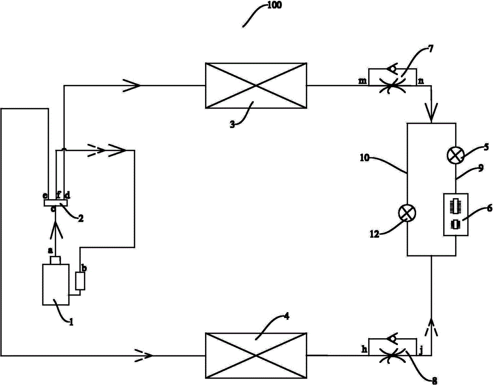
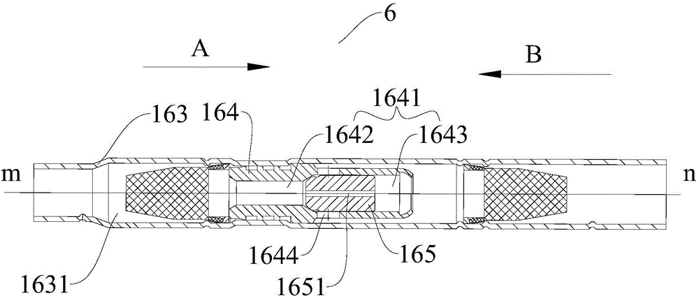
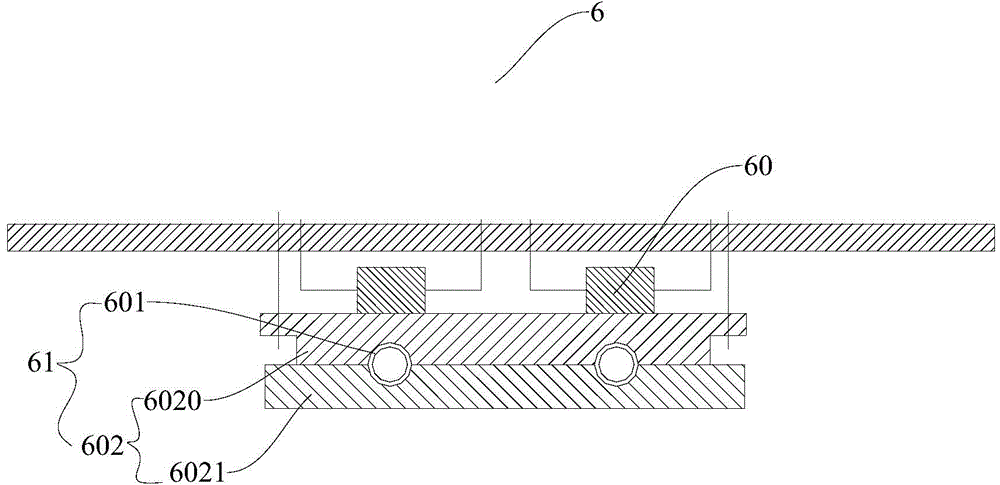
The invention discloses an air conditioner. The air conditioner comprises a compressor, a reversing component, an outdoor heat exchanger, an indoor heat exchanger, a first single-way throttle valve, a second single-way throttle valve, a first coolant flow path and a second coolant flow path both which are connected in parallel, and an electronic control radiator unit. The first single-way throttle valve comprises a first valve port and a second valve port, and the first valve port is connected with the outdoor heat exchanger. The second single-way throttle valve comprises a third valve port and a fourth valve port, and the third valve port is connected with the indoor heat exchanger. The first coolant flow path and the second coolant flow path are in series connected between the second valve port and the fourth valve port respectively, the first coolant flow path is in series connected with a first control valve and the second coolant flow path is in series connected with a second control valve. The electronic control radiator unit comprises an electronic control element and a radiator component, the radiator component is in series connected with the first coolant flow path. According to the air conditioner, condensed water cannot be generated on the electronic control element and the temperature of the electronic control element cannot be reduced to a lower valve.

Description

Technical field [0001] The present invention relates to the technical field of air conditioners, and in particular to an air conditioner. Background technique [0002] With the development of air conditioning technology, inverter air conditioners have been widely used in the industry. However, in the outdoor electronic control system of the inverter air conditioner, the inverter module generates a lot of heat, which limits the high frequency operation of the compressor in a high temperature environment. Most of the currently used electronically controlled heat dissipation methods are mostly metal heat sinks for heat dissipation through air convection. However, in an outdoor high temperature environment, this heat dissipation method has poor heat dissipation. The usual method is to reduce the operating frequency of the compressor and reduce the electric control heating to ensure the normal operation of the air conditioner. It greatly affects the cooling effect of the inverter ai...

Claims


Application Information

Patent Timeline
IPC IPC(8): F24F1/24F24F11/02F24F13/22F25B41/04F25B41/06F25B41/20F25B41/34
CPCF24F1/16F24F1/24F24F11/30F24F11/83F24F2110/10F24F11/84F25B41/30F25B41/31F25B41/20Y02B30/70
Inventor 韩宇李金波陈明瑜
Owner GD MIDEA AIR-CONDITIONING EQUIP CO LTD
Learn More