A kind of vertical shaft integral pouring section wall seat and vertical shaft integral pouring section wall seat construction method

A technology of integral pouring and construction method, which is applied in shaft equipment, earthwork drilling, wellbore lining, etc. It can solve the problems that the position of the final hole is difficult to exceed the range of the barren diameter, the radius of the curtain is small, and the grouting effect is poor.

Inactive Publication Date: 2017-02-22
CHINA COAL ENERGY HEILONGJIANG COAL CHEM
View PDF5 Cites 0 Cited by
  • Summary
  • Abstract
  • Description
  • Claims
  • Application Information

AI Technical Summary

Problems solved by technology

[0009] The purpose of the present invention is to solve the problem that the water-exploring drilling rig arranged in the prior art can only be located inside the inner wall of the wellbore. Under a certain drilling inclination, the position of the final hole is difficult to exceed the range of the barren diameter, and the radius of the formed curtain is small, which is difficult for grouting. A construction method for the wall seat of the integral pouring section of the vertical shaft and the wall seat of the integral pouring section of the vertical shaft due to the problem of poor effect

Method used


Image

  • A kind of vertical shaft integral pouring section wall seat and vertical shaft integral pouring section wall seat construction method

Examples


specific Embodiment approach 1

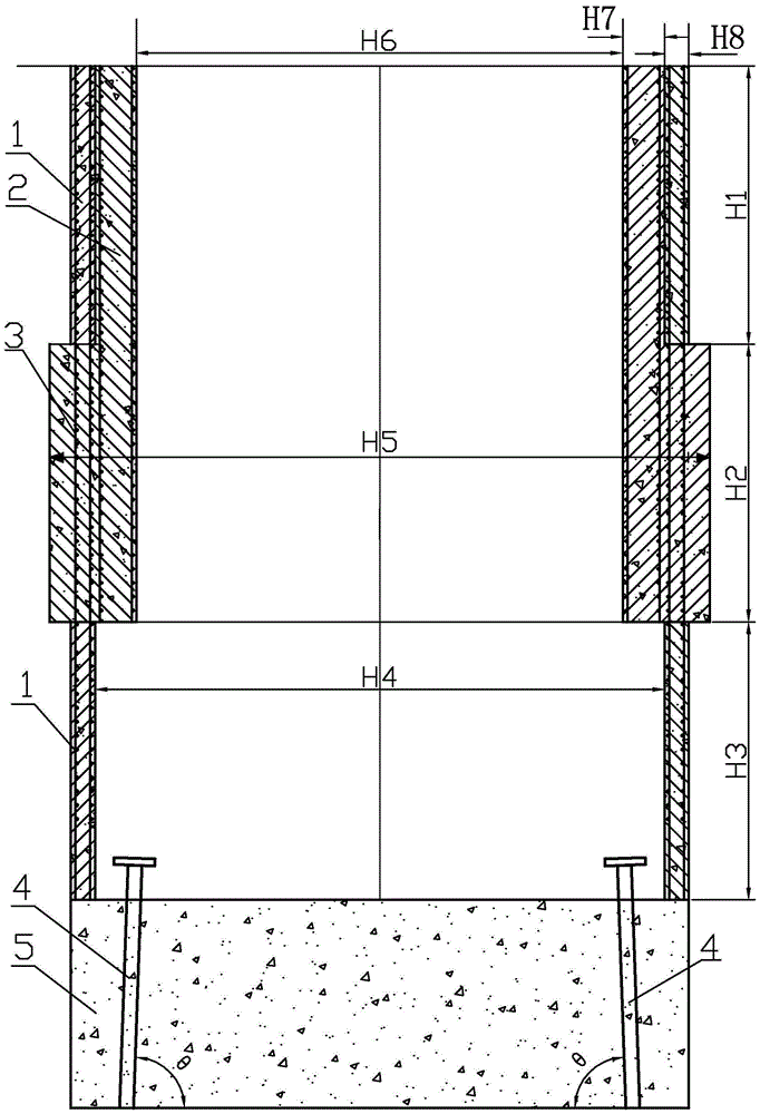
[0025] Specific embodiment one: combination figure 1 To explain this embodiment, the wall seat of the integral casting section of the vertical shaft described in this embodiment includes the outer wall 1, the inner wall 2, the wall seat 3, two water detection orifice pipes 4, and the grouting pad 5, two water detection The orifice pipes 4 are respectively buried in the grouting pad 5, the well wall base 3 is connected with the outer wall of the well, the bottom end of the well wall base is flush with the bottom end of the well inner wall 2, the well inner wall 2 is connected with the well outer wall 1, and the upper end of the well inner wall 2 It is flush with the upper end surface of the outer wall of the well; the outer well wall 1, the inner well wall 2 and the well wall seat 3 are made of concrete and steel bars.

[0026] Effects of this implementation:

[0027] The basic plan of this implementation mode is that the shaft is dug and built to the wall seat, and the large secti...

specific Embodiment approach 2

[0031] Specific embodiment two: this embodiment is different from specific embodiment one in that: the height of the outer well wall 1 is the freezing depth of the shaft or the height of the designed casing wall section is designed according to actual geological conditions; the inner diameter H4 of the outer well wall 1 is 6m ~12m; the wall thickness H8 of the outer wall 1 of the well is 0.35~0.6m. Other steps and parameters are the same as in the first embodiment.

specific Embodiment approach 3

[0032] Specific embodiment three: This embodiment is different from specific embodiment one or two in that: the inner wall 2 of the wellbore is the freezing depth of the wellbore or the height of the designed casing wall; the inner diameter (net diameter of the wellbore) H6 of the well inner wall 2 is 5m~10m ; The wall thickness H7 of the inner wall 2 of the well is 0.5 to 1.0m. The other steps and parameters are the same as in the first or second embodiment.


PUM


Abstract

The invention provides a vertical shaft overall pouring section walling crib and a vertical shaft overall pouring section walling crib construction method. The problems that a water detection drilling machine only can be arranged on the inner side of the inner wall of a shaft in the prior art, under the condition of certain drilling angle inclination, the position of a last hole can hardly exceed the range of the diameter of a pierced pipe, the radius of a formed heavy curtain is small, and the grouting effect is poor are solved. The vertical shaft overall pouring section walling crib comprises an outer shaft wall, an inner shaft wall, a shaft walling crib body, two water detection hole pipes and a grout stop pad. The two water detection hole pipes are embedded in the grout stop pad. The shaft walling crib body is connected with the outer shaft wall. The bottom end face of the shaft walling crib body is flush with the bottom end face of the inner shaft wall. The inner shaft wall is connected with the outer shaft wall. The upper end face of the inner shaft wall is flush with the upper end face of the outer shaft wall. The invention further relates to the vertical shaft overall pouring section walling crib construction method. The vertical shaft overall pouring section walling crib and the vertical shaft overall pouring section walling crib construction method are used for vertical shaft construction.

Description

Technical field [0001] The invention relates to the field of construction methods for integral pouring section wall seats and vertical shaft integral pouring section wall seats, in particular to a vertical shaft integral pouring section wall seat and vertical shaft integral pouring section wall seat construction methods. Background technique [0002] In the prior art, after the wall seat has reached the designed height, the grouting pad is poured, and then the wall seat is poured and the inner wall is sleeved. The next step of water exploration can only be arranged on the inner wall side, and the final hole must be ensured Exceeding the waste path, the radial inclination angle must be increased, which brings certain difficulties to the drilling work. At the same time, the drilling depth is also limited, which cannot achieve the ideal grouting curtain effect. [0003] For example, the wellbore inspection drilling data of No. 12-1 calculates that the wellbore water inflow is 347.65m3...

Claims


Application Information

Patent Timeline
Patent Type & Authority Patents(China)
IPC IPC(8): E21D5/11
CPCE21D5/11
Inventor 李安光王正忠孔祥柯毕玉成高殿军谢玉祥吕德
Owner CHINA COAL ENERGY HEILONGJIANG COAL CHEM
Why Eureka
Try Eureka