Hydraulic drive oil pumping system for oil well

A liquid flooding and oil pumping technology, which is applied in wellbore/well components, production fluid, earthwork drilling and production, etc. It can solve the problems of unbalanced upstroke and downstroke loads, etc.

Active Publication Date: 2015-04-22
PETROCHINA CO LTD
View PDF11 Cites 4 Cited by
  • Summary
  • Abstract
  • Description
  • Claims
  • Application Information

AI Technical Summary

Problems solved by technology

[0007] Aiming at the defect of unbalanced upstroke and downstroke loads in the open hydraulic piston pump system of the prior art, the present invention provides an oil well fluid flooding pumping system, and the technical scheme is as follows:

Method used


Image

  • Hydraulic drive oil pumping system for oil well
  • Hydraulic drive oil pumping system for oil well
  • Hydraulic drive oil pumping system for oil well

Examples


Embodiment approach

[0059] Another embodiment of the present invention for delivering high-pressure power fluid to the reversing mechanism and outputting formation fluid is:

[0060] Please also see Figure 7 , Figure 10 with Figure 11 .

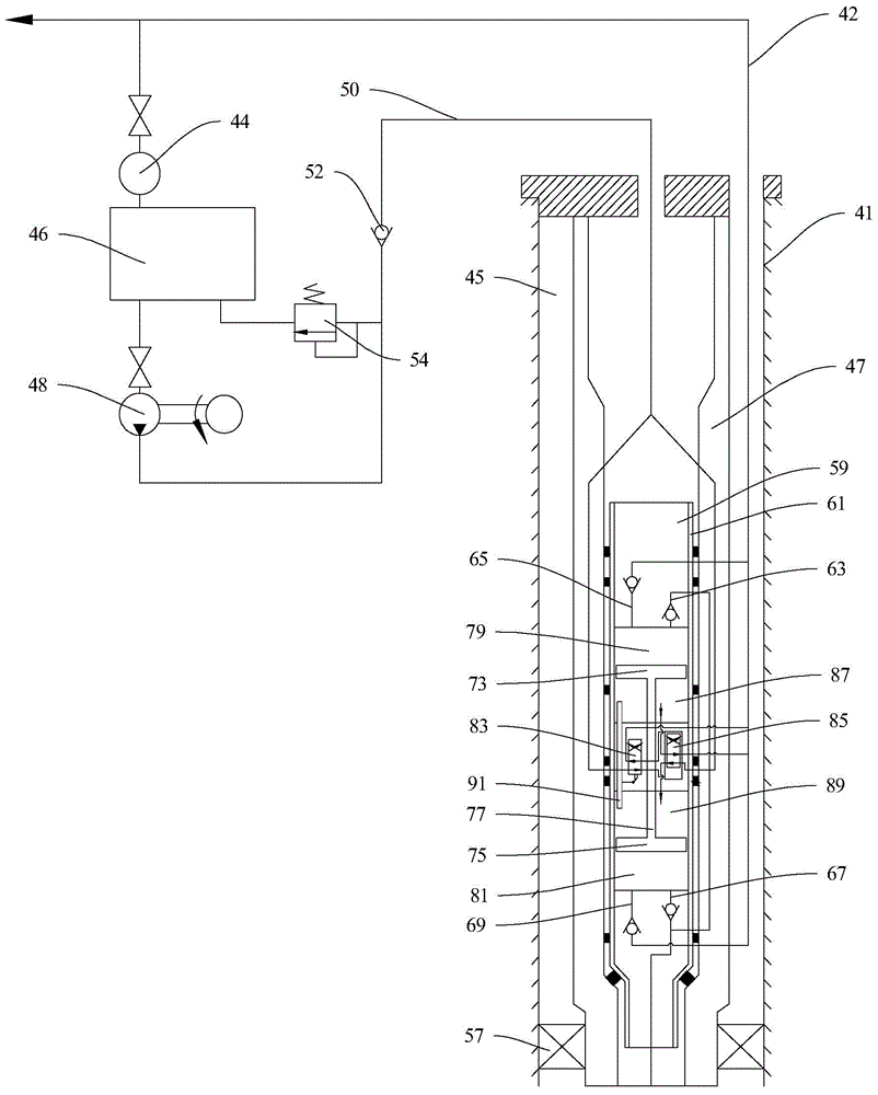
[0061] A third passage 62 is also arranged in the pipe wall of the first pipe string 47 along its axial direction, and the first port 97, the seventh port 103, the second pipeline 65 and the fourth pipeline 69 are connected with the first The three channels 62 are connected.

[0062] The first pipe string 47 is sleeved with a second pipe string 60, the oil well pump core body 61 can be sealed and sleeved in the second pipe string 60, and the oil well pump core body 61 and the wellhead A second annulus 40 is formed between the first pipe string 47 and the second pipe string 60 , and the second annulus 40 communicates with the third channel 62 .

[0063] The working process of this embodiment is:

[0064] When the first piston 73 pushes the connecting rod...


PUM


Abstract

The invention discloses a hydraulic drive oil pumping system for an oil well. The hydraulic drive oil pumping system for the oil well comprises a first two-position four-way reversing valve and a second two-position four-way reversing valve. The third port and the fourth port of the first two-position four-way reversing valve are communicated with the second two-position four-way reversing valve, and the second port of the first two-position four-way reversing valve is alternatively communicated with the third port and the fourth port; high-pressure power fluid entering through the second port enters the second two-position four-way reversing valve through the third port or the fourth port and pushes a valve element of the second two-position four-way reversing valve to move, so that the eighth port of the second two-position four-way reversing valve is alternatively communicated with the fifth port and the sixth port of the second two-position four-way reversing valve, and then high-pressure power fluid entering through the eighth port enters a third cavity or a fourth cavity through the fifth port or the sixth port and pushes a piston to move. According to the hydraulic drive oil pumping system, load balancing of the piston is achieved, the problem that in the prior art, oil pumping is carried out only through the single upstroke is solved, and production efficiency is greatly improved.

Description

technical field [0001] The invention belongs to the technical field of artificial lift for oil and gas field exploitation, and in particular relates to an oil well fluid flooding pumping system. Background technique [0002] The existing artificial lift technology can be divided into two categories: rod lift and rodless lift. The hydraulic piston pump used in the oil field belongs to the rodless lifting. The hydraulic piston pump system is a hydraulically driven rodless pumping equipment. It is a kind of equipment used to lift oil from the oil well. After the power fluid is pressurized, it is pumped into the downhole to drive the piston and the main control slide valve in the oil cylinder through the oil pipe or a special channel, so that the fluid motor can reciprocate up and down, thereby lifting the oil well output fluid to the surface. [0003] According to whether the produced fluid is mixed with the anaerobic fluid, the hydraulic piston pump system includes a closed s...

Claims


Application Information

Patent Timeline
IPC IPC(8): E21B43/00
CPCE21B43/00
Inventor 张建军刘猛朱拾东师俊峰舒勇凌芬琴赵瑞东
Owner PETROCHINA CO LTD
Why Eureka
Try Eureka